Chapter 3. 3 Installing the 40V/H-1
3.1 3.1 Installing in vaults
The 40V/H-1 is a sensitive instrument designed to measure extremely small movements of the ground. These movements are the sum of all the vibrations arriving at the instrument: as well as distant earthquakes and nearby tremors, the ground responds to surf on nearby beaches, quarry blasts, heavy machinery, traffic, and even people moving around the building. Temperature changes and air currents in the same room as the sensor can also affect its output.
3.1.1 Choosing a location
When studying natural earth movements, any other effects introduce unwanted noise into the system. It is therefore important to choose an appropriate site for the instrument, ideally in an underground vault with the sensor installed on a concrete pier that is in direct contact with the bedrock.

This set-up has a number of advantages:
It is installed below ground. Most man-made noise tends to travel along the surface, and natural microseisms (tiny natural flexings of the Earth's crust) also occur near the surface.
Good contact with bedrock means that the signals accurately reflect earth motions; seismic waves do not have to travel through layers of soft soil and sediment.
If the vault is inside a larger structure, its foundations are separated from the pier, so that nearby vibrations are not transmitted to the sensor.
A high-quality seismic vault can be incorporated into the construction plans of a new building at relatively low cost. However, if you are not in a position to build a dedicated vault, you can still reduce noise to a satisfactory level by
installing below ground, in the basement or sub-basement of an existing building;
placing the sensor directly on a cement floor to improve contact; and
locating the sensor in a quiet corner away from people and machinery (e.g. air conditioning and heating systems, elevators, etc.)
Installation on higher floors is not recommended, especially for horizontal sensors, since any “give” in the floor near the sensor will cause it to tilt slightly and register a signal.
3.1.2 Temperature stability
The 40V/H-1 can operate over a wide temperature range (–10 °C to +75 °C). However, the sensor mass is sensitive to fluctuations in local temperature. This affects the response of the instrument at long periods. Sunlight and other bright lights can also cause small mechanical stresses that will be detected by the sensor. You can minimise these effects by
installing in a basement, where the temperature is normally more stable than above ground;
locating the sensor in a dark, protected corner, and
enclosing it in an insulated box (expanded polystyrene works very well). This also helps protect the sensor from air currents.

3.1.3 Other considerations
The sensor and cables should be situated well away from other electrical cables and appliances. Stray radiation from these sources may interfere with the sensor's electronics.
The sensor should be placed on a smooth, level surface free from cracks. Small cracks tend to open and close slightly with changes in humidity and temperature, causing the surface to move slightly.
All three of the sensor's metal feet must make good contact with the floor.
The signal cable from the sensor should rest loosely on the ground nearby, so that vibrations are not transmitted along it.
If your recording or digitizing equipment has front-panel indicators or connectors, make sure it can be reached without disturbing the sensor.
The digitiser's GPS unit needs to be in a location where it can see as many satellites as possible. A location with a good view of the sky, preferably down to the horizon, is recommended. If you are in the Northern Hemisphere, make sure as much of the southern sky as possible is visible. Conversely, in the Southern Hemisphere, make sure the GPS can see a large area of sky to the north.
The GPS unit is supplied with a 15m cable to the digitizer.
3.2 3.2 Installing in pits
For outdoor installations, high-quality results can be obtained by constructing a seismic pit.

Depending on the time and resources available, this type of installation can suit all kinds of deployment, from rapid temporary installations to medium-term telemetered stations.
Ideally, the sensor should rest directly on the bedrock for maximum coupling to surface movements. However, if bedrock cannot be reached, good results can be obtained by placing the sensor on a granite pier on a bed of dry sand.
Prepare a hole of 60 – 90 cm depth to compacted subsoil, or down to the bedrock if possible.
On granite or other hard bedrock, use an angle grinder to plane off the bedrock at the pit bottom so that it is flat and level. Stand the instrument directly on the bedrock, and go to step 7.
On soft bedrock or subsoil, you should install a pier as depicted below.

Pour a layer of loose, fine sand into the pit to cover the base. The type of sand used for children's sand-pits is ideal, since the grains are clean, dry and within a small size range. On top of the sand, place a smooth, flat granite plinth around 20 cm across, and shift it to compact the sand and provide a near-level surface.

Placing a granite plinth on a sand layer increases the contact between the ground and the plinth, and improves the performance of the instrument. There is also no need to mix concrete or to wait for it to set, as in step 4.
Alternatively, if time allows and granite is not available, prepare a concrete mix with sand and fine grit, and pour it into the hole. Agitate (“puddle”) it whilst still liquid, to allow it to flow out and form a level surface, then leave to set. Follow on from step 7.
Puddled concrete produces a fine-textured, level floor for siting the seismometer. However, once set hard, the concrete does not have the best possible coupling to the subsoil or bedrock, which has some leeway to shift or settle beneath it.
Alternatively, for the most rapid installation, place loose soil over the bottom of the pit, and compact it with a flat stone. Place the seismometer on top of this stone. This method emulates that in step 3, but can be performed on-site with no additional equipment.
Set up the instrument as described in Section 3.1, “Installing in vaults” (steps 4 to 9).
The instrument must now be shielded from air currents and temperature fluctuations. This is best done by covering it with a thermal shield.
An open-sided box of 5 cm expanded polystyrene slabs is recommended. If using a seismic plinth on sand (from steps 3–4 or 5), ensure that the box is firmly placed in the sand, without touching the plinth at any point. In other installations, tape the box down to the surface to exclude draughts.
Alternatively, if a box is not available, cover the instrument with fine sand up to the top.
The sand insulates the instrument and protects it from thermal fluctuations, as well as minimizing unwanted vibration.
Ensure that the sensor cable is loose and that it exits the seismometer enclosure at the base of the instrument. This will prevent vibrations from being inadvertently transmitted along the cable.
Cover the pit with a wooden lid, and back-fill with fresh turf.
3.2.1 Other installation methods
The recommended installation methods have been extensively tested in a wide range of situations. However, past practice in seismometer installation has varied widely.
Some installations introduce a layer of ceramic tiles between a rock or concrete plinth and the seismometer (left):


However, noise tests show that this method of installation is significantly inferior to the same concrete plinth with the tiles removed (right). Horizontal sensors show shifting due to moisture trapped between the concrete and tiling, whilst the vertical sensors show "pings" as the tile settles.
Other installations have been attempted with the instrument encased in plaster of Paris, or some other hard-setting compound (left):


Again, this method produces inferior bonding to the instrument, and moisture becomes trapped between the hard surfaces. We recommend the use of fine dry sand (right) contained in a box if necessary, which can also insulate the instrument against convection currents and temperature changes. Sand has the further advantage of being very easy to install, requiring no preparation.
 Finally, many pit installations have a large space around the seismometer, covered with a wooden roof. Large air-filled cavities are susceptible to currents which produce lower-frequency vibrations, and sharp edges and corners can give rise to turbulence. We recommend that a wooden box is placed around the sensor to protect it from these currents. Once in the box, the emplacement may be backfilled with fresh turf to insulate it from vibrations at the surface, or simply roofed as before.
By following these guidelines, you will ensure that your seismic installation is ready to produce the highest quality data.
3.3 Levelling
The CMG-40V/H-1 can operate satisfactorily as long as its axis is within around 2.5° of the vertical.
Horizontal sensors are more sensitive to tile than are vertical sensors. This is because tilting a horizontal sensor produces an extra acceleration proportional to the sine of the tilt angle which, at small angles, is close to the angle itself. Tilting a vertical sensor produces an acceleration proportional to the cosine of the tilt angle, which varies much less at small angles, being approximately unity.
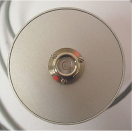
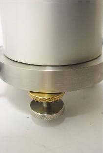
Because of this, the CMG-40H-1 horizontal instrument is provided with a bubble level on the top surface which can be used to ensure that the axis is correctly oriented. Both horizontal and vertical sensors have three adjustable stainless steel feet.
|
|
To level the sensor:
Unlock a foot by screwing the brass lock downwards (to your left, as you look at the instrument). After a few turns, you will be able to turn the foot itself;
Screw the foot in or out as required. Turning the foot to your left will cause it to lengthen; turning it to the right will shorten it;
If necessary, unlock and adjust the other two feet;
Finally, lock all three feet by screwing the brass locks upwards (to your right) until they make contact with the base and the feet will no longer turn. Do not over-tighten the brass lock.