Chapter 2. Introduction
The 5T Compact is a three-axis, strong-motion, force-feedback accelerometer in a sealed case. The accelerometer is self-contained except for its 10 – 36 V power supply, which can be provided through the same cable that carries the analogue data. An internal DC–DC converter ensures that the sensor is completely electrically isolated. Optionally, this converter can be omitted, in which case an external ±12 Volt DC three-way or 'dual rail' power supply is required. Sensors with this option have substantially lower power requirements than those fitted with the DC–DC converter.
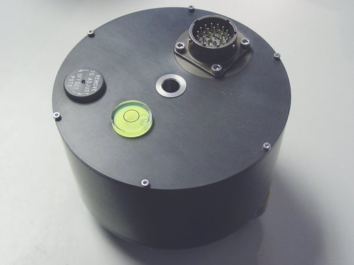
The 5T Compact system combines low-noise components with high feedback loop gain to provide a linear, precision transducer with a very large dynamic range. In order to exploit the entire dynamic range, two separate outputs - high and low gain - are provided. Nominally, the high gain outputs are set to output a signal 10 times stronger than the low gain outputs.
The 5T Compact sensor outputs are all differential with an output impedance of 47 Ω. A single signal ground line is provided as a return line for all the sensor outputs.
Full-scale low-gain sensitivity is available from 4.0 g down to 0.1 g. The most common configuration is for the 5T Compact unit to output 5 V single-ended output for 1 g (≈ 9.81 ms-2) input acceleration. The standard frequency pass band is flat to acceleration from DC to 100 Hz (although other low pass corners from 50 Hz to 100 Hz can be ordered.) A high frequency option provides flat response from DC to 200 Hz.
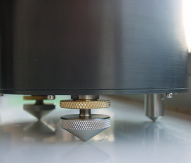 Each accelerometer is delivered with a detailed calibration sheet showing its serial number, measured frequency response, sensor DC calibration levels and the transfer function in poles/zeroes notation. Installation is simple, using a single fixing bolt to attach the sensor to a hard surface. If required, you can also level the sensor using its two adjustable levelling feet.
Optionally, you can use a Güralp Hand-held Control Unit (HCU) and breakout box to distribute power and calibration signals to the sensor and to receive the signals it produces. It is available in standard, rack-mounted and water-resistant portable formats.
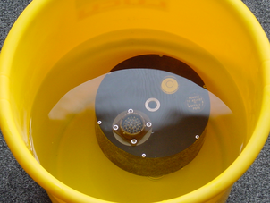 The accelerometer housing itself is completely waterproof, with a hard anodised aluminium body and “O”-ring seals throughout. 5T Compact instruments have been tested for long periods of total immersion in water.