Chapter 1. Introduction
The Güralp 5TCDE accelerometer is a three-axis, strong-motion, force- feedback accelerometer packaged together with a 24-bit digitiser and a flexible data acquisition and storage unit, all in a single sealed case. The entire system is self- contained except for its power supply and GPS receiver, which is used for time-stamping seismic data.
The 5TC system combines low-noise components with a high feedback-loop gain to provide a linear, precision transducer with a very large dynamic range. In order to exploit the whole dynamic range, two separate outputs are available, one with high gain and one with low gain. Normally, the high gain outputs are set to output a signal 10 times stronger than that from the low gain outputs. See section 1.1 for details.
Full-scale low-gain sensitivity is available from 4.0 g down to 0.1 g. The most common configuration is for the 5TC unit to output 5 V single- ended output for 1 g (≈ 9.81 ms-2) input acceleration. The standard frequency pass band is flat to acceleration from DC to 100 Hz (although other low pass corners can be ordered.) A high frequency option provides flat response from DC to 200 Hz.
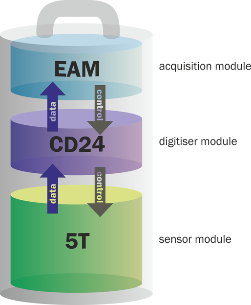
The integrated digitiser is a CD24, a low-noise, 24-bit ADC module specifically designed for seismic data. The built-in digital signal processor (DSP) provides simultaneous, multiple sample-rate data streams at user-selectable rates. Up to 4 streams of data for each component are available at sample rates from 1 to 1000 samples per second. A precision microprocessor-controlled time-base synchronizes the analogue-to-digital converters to the DSP and provides time-stamps for data. A separate microprocessor system handles configuration and sensor control, including mass centring and calibration.
The integrated data acquisition system is a EAM, which provides serial and Ethernet communications, along with a convenient web-based interface to all functions, including digitiser and sensor configuration and control. It can act as a data recorder as well as a protocol converter and communications controller. Based around the powerful and stable Linux operating system, the EAM offers unrivalled flexibility, even including the ability to run user-installed scripts.
Each instrument is delivered with a detailed calibration sheet showing its serial number, measured frequency response in both the long period and the short period sections of the seismic spectrum, sensor DC calibration levels, and the transfer function in poles/zeros notation.
1.1 Setting the gain
The built in 5TC sensor has a very large dynamic range. In order to exploit the whole of this range, two separate outputs are available, one with high gain and one with low gain. Normally, the high gain outputs are set to output a signal 10 times stronger than that from the low gain outputs. Only one set of outputs – low gain or high gain – is sent to the digitiser, the selection being made using internal jumpers.
Note: To change the gain, it is necessary to open the instrument. This work must be carried out in a clean environment in order to prevent contamination of the mechanical components by air-borne dust.
Caution: ESD: The 5TCDE include components which can be damaged by electrostatic discharge. If you need to open the instrument, work on a properly grounded dissipative surface and wear a suitable grounded wristband. Ground yourself by touching an earthed conductor before handling any of the circuit boards.
In order to change the gain-setting jumpers, remove the instrument's lid as follows:
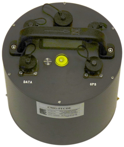
Use a large, flat-bladed screwdriver to remove the pressure-release screw located on the instrument's lid next to the bubble-level.
Note: If working at a high altitude location, the internal pressure might be significantly higher than the ambient pressure and the pressure relief screw, once released, may fly away with considerable force.
Use a small, flat-bladed screwdriver to remove the six small screws located around the edge of the top of the lid.
Note the location of the lid with respect to the body. Use a pencil or adhesive tape to mark both so that the instrument can be reassembled in the correct orientation.
Using a medium, flat-bladed screwdriver, gently prise the lid away from the body. A slot is provided in the top of the cylinder for this purpose.
Note: The lid-to-body seal uses 'O'-rings. Take care that the lid does not suddenly fly off when this seal is broken.
Lift the lid and the attached electronics vertically out of the cylindrical body and disconnect the ribbon cable at either end, noting the orientation of the cable.
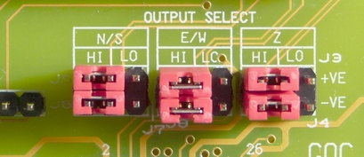
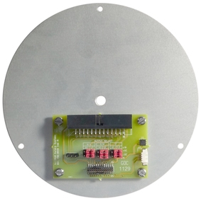 Looking down into the body of the instrument, you will see a small printed circuit board mounted on an aluminium bulkhead. This board contains the gain-setting jumpers, which are coloured red to aid identification.
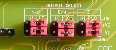
Each component (vertical, North/South and East/West) has two associated jumpers (one for each leg of the differential connection) and these must always be moved in pairs. It is possible to select different gains for different channels but this is rarely desirable. Consult the markings on the printed circuit board and the pictures below to select the desired gain:
1.1.1 Jumper configuration for low gain operation
Arrange the jumpers as in the picture below:
1.1.2 Jumper configuration for high gain operation
Arrange the jumpers as in the picture below:
1.1.3 Reassembly
Once the desired gain selection has been made, reconnect the ribbon cable and gently lower the lid onto the instrument, taking care not to knock the electronic assemblies or snag any cables. Ensure that the lid is rotated to the correct orientation using the marks you made previously and then gently ease it over the 'O'-ring seal and into place. Secure using the six small screws and, finally, replace the large pressure release screw.
1.2 Connections
The Güralp 5TCDE has five connectors on the top panel, the uses of which are described in this section.
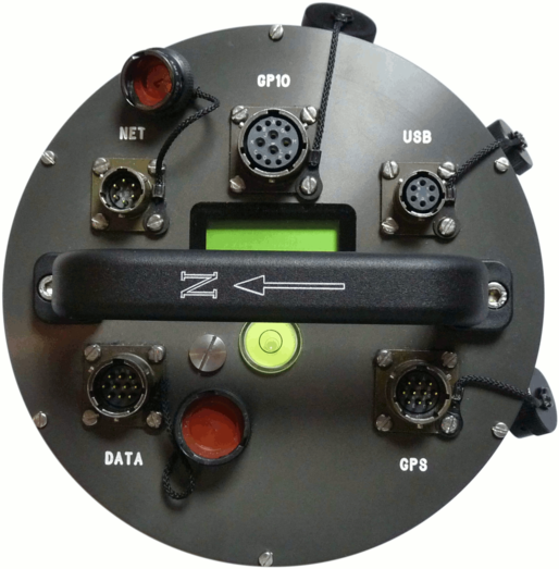
1.2.1 DATA
The DATA port is the power input and also a general-purpose serial port. It is a command line terminal running at 115,200 Baud in the default configuration but it can also be used for GCF output (suitable for serial connection to Scream!) , PPP network connections, inbound GCF (from a digital instrument, for example), NMEA functions, TCP serial conversion or as a recorder to store and forward data from any instrument with a serial output.
1.2.2 NET
The NET port is a 100BASE-TX Ethernet connection. The supplied cable supports connection to a hub, switch or router. If direct connection to a PC or laptop is desired, an optional cross-over cable can be ordered.
1.2.3 GPIO
The GPIO (General Purpose Input/Output) port fulfils three functions: it provides a serial console to the EAM, which can be used for monitoring, configuration and control; it provides USB access from a PC or laptop to the internal FLASH storage for data collection (Use of this feature is described in the EAM manual, MAN-EAM-0003 ) and it provides a number of tri-state lines which can be used to control or monitor external equipment. One application is as tamper detection lines, which can be connected to external switches and monitors as part of a secure installation.
1.2.4 USB
The USB port allows connection of an external USB storage device for data collection. It is also possible to perform firmware upgrades using this port in situations where internet access is not available.
1.2.5 GPS
The GPS port allows connection of a GSL GPS receiver for use as a timing source for time-stamping seismic data. An additional serial port, ttySA2, is also available on this connector. It can be used for any of the functions available from the DATA connector (see section 1.2.1, above).