Chapter 5. Connections
5.1 Analogue connections
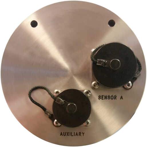
The analogue connector panel of the Affinity has one or two SENSOR connectors (depending on the model) and an AUXILIARY connector. The pin-outs for these connectors are given in the following sections.
Note: Early models did not provide power via the AUXILIARY connector.
The auxiliary connector provides a differential input to the fourth full-rate channel and single-ended inputs to ten of the sixteen multiplexed inputs. (The other six are connected internally for use as mass position channels on the main SENSOR A and SENSOR B inputs.)
5.1.1 SENSOR A and SENSOR B
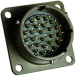
This is a standard twenty-six-pin bayonet plug, conforming to MIL‑DTL‑26482 (formerly MIL‑C‑26482). A typical part-number is 02E‑16‑26P although the initial “02E” varies with manufacturer. Suitable mating connectors have part-numbers like ***‑16‑26S and are available from Amphenol, ITT Cannon and other manufacturers. |
|
Pin | Function | Pin | Function | |
A | Vertical velocity non-inverting input | P | Calibration signal | |
B | Vertical velocity inverting input | R | Vertical calibration enable | |
C | N/S velocity non-inverting input | S | N/S calibration enable | |
D | N/S velocity inverting input | T | E/W calibration enable | |
E | E/W velocity non-inverting input | U | Centre * | |
F | E/W velocity inverting input | V | not connected | |
G | Vertical mass position input | W | Unlock * | |
H | not connected | X | Lock * | |
J | N/S mass position input | Y | Digital (logic signal) ground | |
K | Busy indicator LED | Z | not connected | |
L | E/W mass position input | a | not connected | |
M | not connected | b | Power 0 V & digital ground | |
N | Signal ground | c | Power output +9 to +36 VDC |
* Sensor control lines automatically detect whether connected instruments use "active-low" or "active-high" logic.
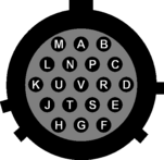
| Wiring details for the compatible socket, ***‑16‑26S, as seen from the cable end (i.e. during assembly). |

Note: Early models provided RS232/RS422 sensor control lines via this connector. This functionality is no longer available.
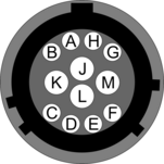
5.1.2 AUXILIARY input
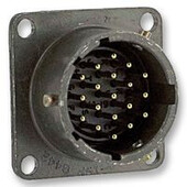
This is a standard nineteen-pin bayonet plug, conforming to MIL‑DTL‑26482 (formerly MIL‑C‑26482). A typical part-number is 02E‑14‑19P although the initial “02E” varies with manufacturer. Suitable mating connectors have part-numbers like ***‑14‑19S and are available from Amphenol, ITT Cannon and other manufacturers. |
|
Pin | Function | Pin | Function | |
A | SENSOR B auxiliary / calibration channel non-inverting (+ve) | L | SENSOR A and multiplexed inputs signal ground | |
B | SENSOR B auxiliary / calibration channel inverting–ve | M | Multiplexed input E / Aux 10 | |
C | SENSOR B Signal ground | N | Digital ground | |
D | Multiplexed input A / Aux 6 | P | Power output -ve | |
E | Multiplexed input B / Aux 7 | R | Multiplexed input F / Aux 11 | |
F | Multiplexed input C / Aux 8 | S | Multiplexed input G / Aux 12 | |
G | Power output +ve | T | Multiplexed input H / Aux 13 | |
H | Multiplexed input D / Aux 9 | U | Multiplexed input J / Aux 14 | |
J | SENSOR A auxiliary / calibration channel non-inverting (+ve) | V | Multiplexed input K / Aux 15 | |
K | SENSOR A auxiliary / calibration channel inverting–ve |
| Wiring details for the compatible socket, ***‑14‑19S, as seen from the cable end (i.e. during assembly). |
Note: Early models did not provide power via the AUXILIARY connector.
5.2 Digital connections
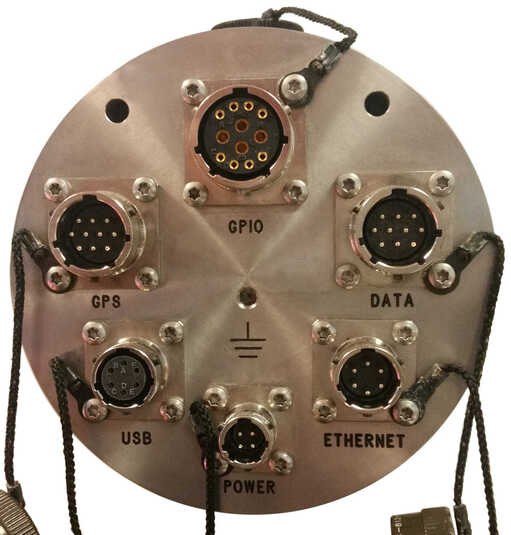
The Affinity has six connectors on the digital connection panel, the pin-outs and uses of which are described in this section.
5.2.1 Connector usage summary
5.2.1.1 DATA
The DATA port is a general-purpose serial port and it can also be used as alternative power input. It provides a command-line terminal running at 115,200 Baud in the default configuration but it can also be used for GCF output (suitable for serial connection to Scream!), PPP network connections, inbound GCF (from a digital instrument, for example), NMEA functions, TCP serial conversion, a modem answering service or as a recorder to store and forward data from any instrument with a serial output.
5.2.1.2 ETHERNET
The NET port is a 100BASE-TX Ethernet connection. The supplied cable supports connection to a hub, switch or router. If direct connection to a PC or laptop is desired, an optional cross-over cable can be ordered.
5.2.1.3 POWER
The POWER connector functions as the main power input and also provides a switched power outlet for external equipment.
5.2.1.4 USB
The USB port allows connection of an external USB storage device for data collection. It is also possible to perform firmware upgrades using this port in situations where internet access is not available.
5.2.1.5 GPS
The GPS port allows connection of a GSL GPS receiver for use as a timing source for time-stamping seismic data. An additional serial port, ttySA2, is also available on this connector. It can be used for any of the functions available from the DATA connector (see section 5.2.1.1).
5.2.1.6 GPIO
The GPIO (General Purpose Input/Output) port fulfils two functions: it provides a serial console to the Affinity, which can be used for monitoring, configuration and control; and it provides a number of tri-state lines which can be used to control or monitor external equipment. One application is as tamper detection lines, which can be connected to external switches and monitors to form part of a secure installation.
Note: Early models provided access to the internal USB storage via this connector. This functionality is no longer available.
5.2.2 Connector Pin-outs
5.2.2.1 DATA
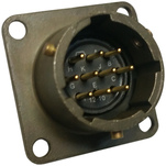
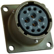
This is a standard ten-pin bayonet plug, conforming to MIL‑DTL‑26482 (formerly MIL‑C‑26482). A typical part-number is 02E‑12‑10P although the initial “02E” varies with manufacturer. Suitable mating connectors have part-numbers like ***‑12‑10S and are available from Amphenol, ITT Cannon and other manufacturers. |
|
Pin | Function |
A | Power input, 0 V |
B | Power input +10 to +28 Volts DC |
C | RS232 CTS |
D | RS232 RTS |
E | External trigger output |
F | External trigger output |
G | RS232 ground |
H | External trigger input |
J | RS232 receive |
K | RS232 transmit |
| Wiring details for the compatible socket, ***‑12‑10S, as seen from the cable end (i.e. during assembly). |

5.2.2.2 ETHERNET
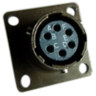
This is a standard six-pin bayonet plug, conforming to MIL‑DTL‑26482 (formerly MIL‑C‑26482). A typical part-number is 02E‑10‑06P although the initial “02E” varies with manufacturer. Suitable mating connectors have part-numbers like ***‑10‑06S and are available from Amphenol, ITT Cannon and other manufacturers. |
|
Pin | Function |
A | Ground |
B | Data transmit +ve (RJ45 pin 1) |
C | Data receive +ve (RJ45 pin 3) |
D | Ethernet auxiliary power output (see section 8.2.3) |
E | Data receive –ve (RJ45 pin 6) |
F | Data transmit –ve (RJ45 pin 2) |
| Wiring details for the compatible socket, ***‑10‑06S, as seen from the cable end (i.e. during assembly). |

5.2.2.3 POWER
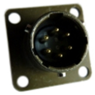
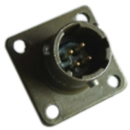
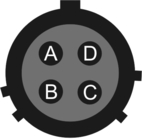
This is a standard four-pin bayonet plug, conforming to MIL‑DTL‑26482 (formerly MIL‑C‑26482). A typical part-number is 02E‑08‑04P although the initial “02E” varies with manufacturer. Suitable mating connectors have part-numbers like ***‑08‑04S and are available from Amphenol, ITT Cannon and other manufacturers. |
|
Pin | Function |
A | Ground |
B | Power input +10 to +28 Volts DC |
C | Not connected |
D | Auxiliary power output (see section 8.2.1) |
| Wiring details for the compatible socket, ***‑08‑04S, as seen from the cable end (i.e. during assembly). |
5.2.2.4 USB
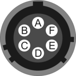
This is a standard six-pin bayonet socket, conforming to MIL‑DTL‑26482 (formerly MIL‑C‑26482). A typical part-number is 02E‑10‑06S although the initial “02E” varies with manufacturer. Suitable mating connectors have part-numbers like ***‑10‑06P and are available from Amphenol, ITT Cannon and other manufacturers. |
|
Pin | Function |
A | +5 Volt DC (USB Type A pin 1) (see section 8.2.11) |
B | Data –ve (USB Type A pin 2) |
C | Data +ve (USB Type A pin 3) |
D | 0 V (USB Type A pin 4) |
E | Shielding |
F | “USB on-the-go” detection (see section 8.2.12) |
| Wiring details for the compatible plug, ***‑10‑06P, as seen from the cable end (i.e. during assembly). |
5.2.2.5 GPS
This is a standard ten-pin bayonet plug, conforming to MIL‑DTL‑26482 (formerly MIL‑C‑26482). A typical part-number is 02E‑12‑10P although the initial “02E” varies with manufacturer. Suitable mating connectors have part-numbers like ***‑12‑10S and are available from Amphenol, ITT Cannon and other manufacturers. |
|
The pin-out is the same as the GPS input of a DM24 digitizer.
Pin | Function |
A | Power 0 V |
B | Power +V |
C | 1pps signal |
D | not connected |
E | Digitizer console transmit |
F | Digitizer console receive |
G | RS232 ground |
H | Digitizer console ground |
J | RS232 transmit to GPS |
K | RS232 receive from GPS |
| Wiring details for the compatible socket, ***‑12‑10S, as seen from the cable end (i.e. during assembly). |
5.2.2.6 GPIO
This is a standard twelve-pin bayonet socket, conforming to MIL‑DTL‑26482 (formerly MIL‑C‑26482). A typical part-number is 02E‑14‑12S although the initial “02E” varies with manufacturer. Suitable mating connectors have part-numbers like ***‑14‑12P and are available from Amphenol, ITT Cannon and other manufacturers. |
|
Pin | Function |
A | Not connected |
B | Not connected |
C | Not connected |
D | Anti-tamper line 3 (see section 8.2.8) |
E | Anti-tamper line 2 (see section 8.2.8) |
F | Anti-tamper line 1 (see section 8.2.8) |
G | Console transmit (RS232 TXD) |
H | Console receive (RS232 RXD) |
J | Not connected |
K | Not connected |
F | Anti-tamper line 1 (see section 8.2.8) |
M | Ground |
| Wiring details for the compatible plug, ***‑14‑12P, as seen from the cable end (i.e. during assembly). |
Note: Early models provided access to the internal USB storage via this connector. This functionality is no longer available.