Chapter 6. Connector pin-outs
Note: Control signals are normally active low, but active high versions can be supplied on request.
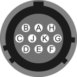
6.1 Break-out box POWER
This is a standard 10-pin military-specification bayonet socket, conforming to MIL-DTL-26482 (formerly MIL-C-26482). A typical part-number is 02E-12-10S although the initial “02E” varies with manufacturer. Suitable mating connectors have part-numbers like ***-12-10P and are available from Amphenol, ITT Cannon and other manufacturers. |
|
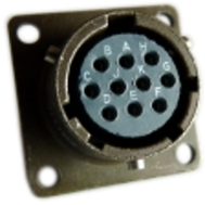
Pin | Function |
A | 0V power |
B | + 12 to 24 V DC power |
C | not connected |
D | not connected |
E | Control signal ground |
F | Hole-lock motor |
G | not connected |
H | not connected |
J | not connected |
K | Hole-lock motor return |
| Wiring details for the compatible plug, ***-12-10P, as seen from the cable end (i.e. when assembling). |
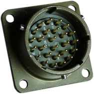
6.2 Break-out box RECORDER and CONTROL
These are standard 26-pin military-specification bayonet plugs, conforming to MIL-DTL-26482 (formerly MIL-C-26482). A typical part-number is 02E-16-26P although the initial “02E” varies with manufacturer. Suitable mating connectors have part-numbers like ***-16-26S and are available from Amphenol, ITT Cannon and other manufacturers. |
|

Pin | Function | Pin | Function |
A | Velocity +ve, vertical channel | P | Calibration signal (all channels) |
B | Velocity –ve, vertical channel | R | Calibration enable (all channels) |
C | Velocity +ve, N/S channel | S | Inclinometer X tilt (optional) |
D | Velocity –ve, N/S channel | T | Inclinometer Y tilt (optional) |
E | Velocity +ve, E/W channel | U | CENTRE |
F | Velocity –ve, E/W channel | V | RS232 RxD |
G | Mass position, vertical channel | W | RS232 TxD |
H | not connected | X | LOCK |
J | Mass position, N/S channel | Y | Control signal ground |
K | not connected | Z | Inclinometer power (optional) |
L | Mass position, E/W channel | a | not connected |
M | not connected | b | 0 V power |
N | Signal ground | c | + 12 to 24 V DC power |
| Wiring details for the compatible socket, ***-16-26S, as seen from the cable end (i.e. when assembling). |
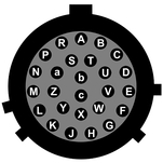
6.3 Break-out box SENSOR
These are standard 26-pin military-specification bayonet plugs, conforming to MIL-DTL-26482 (formerly MIL-C-26482). A typical part-number is 02E-16-26P although the initial “02E” varies with manufacturer. Suitable mating connectors have part-numbers like ***-16-26S and are available from Amphenol, ITT Cannon and other manufacturers. |
|
Pin | Function | Pin | Function |
A | Velocity +ve, vertical channel | P | Calibration signal (all channels) |
B | Velocity –ve, vertical channel | R | Calibration enable (all channels) |
C | Velocity +ve, N/S channel | S | Inclinometer X tilt (optional) |
D | Velocity –ve, N/S channel | T | Inclinometer Y tilt (optional) |
E | Velocity +ve, E/W channel | U | CENTRE |
F | Velocity –ve, E/W channel | V | RS232 RxD |
G | Mass position, vertical channel | W | RS232 TxD |
H | Hole-lock motor | X | LOCK |
J | Mass position, N/S channel | Y | Control signal ground |
K | not connected | Z | Inclinometer power (optional) |
L | Mass position, E/W channel | a | not connected |
M | not connected | b | 0 V power & |
N | Signal ground | c | + 12 to 24 V DC power |
| Wiring details for the compatible socket, ***-16-26S, as seen from the cable end (i.e. when assembling). |
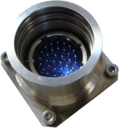
6.4 Instrument
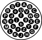
This is a Güralp custom-designed 32-pin plug with pin spacing and layout conforming to MIL-DTL-26482 (formerly MIL-C-26482). The GSL part number is ELM-32P-18FX+MEC-GEN-1002-32W. |
|
Pin | Function | Pin | Function |
A | Hole-lock motor | T | Inclinometer Y tilt (optional) |
B | Hole-lock motor return | U | Inclinometer X tilt (optional) |
C | Inclinometer power (optional) | V | CENTRE |
D | + 12 to 24 V DC power | W | not connected |
E | 0 V power | X | RS232 RxD |
F | Mass position, vertical channel | Y | not connected |
G | Mass position, N/S channel | Z | RS232 TxD |
H | Mass position, E/W channel | a | not connected |
J | Velocity +ve, vertical channel | b | Acc/Vel mode switch* |
K | Velocity –ve, vertical channel | c | not connected |
L | Velocity +ve, N/S channel | d | not connected |
M | Velocity –ve, N/S channel | e | Signal ground |
N | Velocity +ve, E/W channel | f | Control signal ground |
P | Velocity –ve, E/W channel | g | not connected |
R | Calibration signal (all channels) | h | not connected |
S | Calibration enable (all channels) | j | not connected |
| Wiring details for the compatible socket, MEC-GEN-2002-32W, as seen from the cable end (i.e. when assembling). |
6.5 Combined wiring schedule
This table combines the pin-outs for all connectors on the instrument and its break-out box (BoB).
Instrument | BoB | BoB | Function |
A | H |
| Hole-lock motor |
B | b |
| Hole-lock motor return |
C | Z | Z | Inclinometer power (optional) |
D | c | c | + 12 to 24 V DC power |
E | b | b | 0 V power |
F | G | G | Mass position, vertical channel |
G | J | J | Mass position, N/S channel |
H | L | L | Mass position, E/W channel |
J | A | A | Velocity +ve, vertical channel |
K | B | B | Velocity –ve, vertical channel |
L | C | C | Velocity +ve, N/S channel |
M | D | D | Velocity –ve, N/S channel |
N | E | E | Velocity +ve, E/W channel |
P | F | F | Velocity –ve, E/W channel |
R | P | P | Calibration signal (all channels) |
S | R | R | Calibration enable (all channels) |
T | T | T | Inclinometer Y tilt (optional) |
U | S | S | Inclinometer X tilt (optional) |
V | U | U | Centre |
X | V | V | Rs232 RX |
Z | W | W | Rs232 TX |
Y | X | X | (Lock) |
b |
|
| Acc/Vel mode switch* |
e | N | N | Signal ground |
f | Y | Y | Control signal ground |
* The Acc/Vel mode switch pin is used by the automatic centring process to switch the instrument temporarily into a mode where its response at normal frequencies is flat to acceleration, and thus in linear proportion to the mass position. The sensor returns to its operational mode once the centring process is completed.