Chapter 5. Connector pin-outs
5.1 10 m Single flute cable
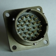
This is a standard 26-pin military-specification bayonet plug, conforming to MIL-DTL-26482 (formerly MIL-C-26482). A typical part-number is 02E-16-26P although the initial “02E” varies with manufacturer. Suitable mating connectors have part-numbers like ***-16-26S and are available from Amphenol, ITT Cannon and other manufacturers. |
|
Pin | Function | Pin | Function |
A | Vertical velocity non-inverting | P | Calibration signal in (±5V max) |
B | Vertical velocity inverting | R | Calibration enable |
C | N/S velocity non-inverting | S | Response 0 (see text) |
D | N/S velocity inverting | T | Response 1 (see text) |
E | E/W velocity non-inverting | U | Centre (see text) |
F | E/W velocity inverting | V | Hole-lock power (12V, 8W) |
G | Vertical mass position | W | not connected |
H | Hole-lock signal (±12V wrt Y) | X | not connected |
J | N/S mass position | Y | Digital ground |
K | Busy (active high, 3.3V via 1kΩ) | Z | RS485 +Data |
L | E/W mass position | a | RS485 -Data |
M | Not connected | b | 0 V power and hole-lock ground |
N | Signal ground | c | Sensor power (9-36V, 200mW) |
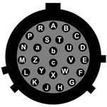
| Wiring details for the compatible socket, ***-16-26S, as seen from the cable end (i.e. when assembling). |
5.2 Surface box
This is a standard 26-pin military-specification bayonet plug, conforming to MIL-DTL-26482 (formerly MIL-C-26482). A typical part-number is 02E-16-26P although the initial “02E” varies with manufacturer. Suitable mating connectors have part-numbers like ***-16-26S and are available from Amphenol, ITT Cannon and other manufacturers. |
|
Pin | Function | Pin | Function |
A | Vertical velocity non-inverting | P* | Calibration signal in (±5V max) |
B | Vertical velocity inverting | R* | Calibration enable |
C | N/S velocity non-inverting | S | Response 0 (see text) all sensors |
D | N/S velocity inverting | T | Response 1 (see text) all sensors |
E | E/W velocity non-inverting | U | not connected |
F | E/W velocity inverting | V | not connected |
G | Vertical mass position | W | not connected |
H | not connected | X | not connected |
J | N/S mass position | Y | Digital ground |
K | Busy (active high, 3.3V via 1kΩ) | Z | not connected |
L | E/W mass position | a | not connected |
M | Not connected | b | not connected |
N | Signal ground | c | not connected |
* Pins P and R are only connected on the first of the five connectors.
| Wiring details for the compatible socket, ***-16-26S, as seen from the cable end (i.e. when assembling). |