Chapter 3. Setting up the CMG-CD24R6EAM
3.1 Initial Installation
Note: Refer to Appendix E on page 31 for information on connector pinouts.
Connect the 10-pin connector on the unit to a GPS receiver using the GPS cable. Position the GPS so that it has a good view of the sky. If you do not have a view of the sky, you can operate the unit without a GPS receiver, but timing information may be inaccurate.
Connect the instruments to the surge arrestors.
Connect the surge arrestors to to the 26-pin connectors in the configuration shown in section 2.3.2.
Use the power cable to connect the 10-pin Power/Data Out connector to a fused 10 – 28 V power source and wait for the system to boot. This can take up to 90 seconds. The LCD display will indicate when the process is complete.
The system is now fully operational and will already be producing data.
The acquisition module can be connected to a PC using a serial cable from the 10-pin Power/Data Out port or over a network using the Ethernet ports.
Data outputs from the EAM can be viewed using the Guralp Systems Scream application. See the manual MAN-SWA-0001 for information on using Scream.
Data outputs from the Lantronix WiPort NR can now be accessed using suitable software.
3.2 Connecting to the Lantronix WiPort NR
The Lantronix WiPort NR has been pre-configured so there should be no reason to change any of the settings. If however you wish to make any changes the following procedure for connecting to the Lantronix WiPort NR should be used:
Connect the acquisition module to a DHCP enabled network and note the IP address.
Enter the IP address into the address bar of an internet browser.
When the Authentication Required window displays enter a User Name of 'admin'. Leave the password blank. Click on OK or press the Enter key.
Once the Lantronix WiPort NR home page appears you can use the menu list on the left to view and configure the settings:
The default settings for the device are given in Appendix A on page 13.
Caution: Making any changes to the default settings may cause the device to stop working.
After making any changes click OK at the bottom of each screen. On completion click on Apply Settings. This will update and reboot the module.
If you are unable to locate the device or have problems connecting, further information is given at Appendix B on page 20.
3.3 Connecting to the CMG-EAM
The CMG-EAM has been pre-configured so there should be no reason to change any of the settings. If however you wish to make any changes to the Low Latency ports the following procedure for connecting to the CMG-EAM should be used:
Connect the acquisition module to a DHCP enabled network and note the IP address.
Enter the IP address into the address bar of an internet browser.
At the EAM homepage click on the User Login link in the menu on the left.
When the Authentication Required window displays enter a User Name of 'root' and a password of 'rootme'. Click on OK or press the Enter key.
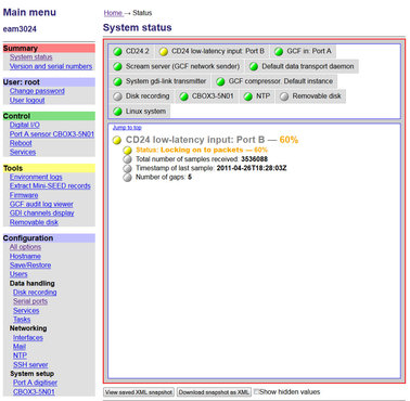
Once the full menu appears on the left you have access to all the configuration and control options.
The right hand part of the widow displays the current status of the system. The links in the main menu will update the main part of the window to the selected configuration and control settings:
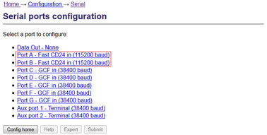
To see the settings for the low-latency ports first click on the Serial Ports link in the main menu then select Port A or Port B from the list that appears:
From the port A or B serial configuration page click on the Fast CD24 input settings link:
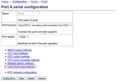
The 5 tabs that appear allow you to the view and change the port settings. The default settings for the ports are given in Appendix A on page 13.
Caution: Making any changes to the default settings may cause the device to stop working.
After making any changes click on the Submit button at the bottom of each screen.
If you are unable to locate the device or have problems connecting, further information is given in the EAM manual: MAN-EAM-0003.
Other menu items in the EAM allow for their control and configuration of the CMG-CD24 digitisers, ports and other connected devices.
Any changes made in the EAM to the CD24 settings will be reflected in the Lantronix WiPort NR data output.
3.4 Using the internal mass storage device
The acquisition module has an internal mass storage device which is accessible via the GPIO port (see section 2.2.1.3).
To write to the internal mass storage device:
Connect to the CMG-EAM as described in section 3.3.
Click on the Disc Recording link in the main menu.
Select Internal USB storage from the Recording destination drop-down menu.
When a USB host, such as a laptop or PC, is connected to the GPIO port, internal circuitry detects the USB power and automatically connects the Flash memory to the GPIO socket, causing it to behave identically to a standard USB memory stick.
When no power is detected at the GPIO port, the Flash memory is available to the system as if it were a standard removable mass storage device. All of the mass storage device recording options described in the CMG-EAM manual MAN-EAM-0003.
3.5 Warning and error reporting
Each component in the station has a predefined warning and error level. The status of the components are indicated on the EAM homepage.
Green indicators are shown when the level is above 70%
Amber warnings are displayed when the level falls below 70%
Red errors are displayed when the level falls below 40%
The status of all components can be monitored and if the level falls below a set percentage a selected output line can be switched from low to high for use by an external indication system.
To configure the status iolines using the web interface select:
Configuration > All options > Status iolines assertion configuration
To configure the status iolines from the command line, start gconfig and select “Status iolines assertion configuration” from the top level menu.
3.5.1 Configurable parameters in simple mode
The configurable parameters for recording data in simple mode are shown below:
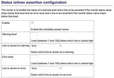
Enable: Activates the status iolines assertion server.
Warning level: Set the level at which the warning signal is to be triggered.
Line to assert on warning: Select the output line from the dropdown list. All output lines are displayed so care should be taken to choose a suitable output line.
Error level: Set the level at which the warning signal is to be triggered. The error level must be less than the warning level.
Line to assert on error: Select the output line from the dropdown list. All output lines are displayed so care should be taken to choose a suitable output line.
3.5.2 Configurable parameters in expert mode
An additional field is displayed in expert mode:

Log level: The drop-down menu controls the level of detail present in log messages. Not all of the standard syslog logging levels are available. The menu offers a choice (in order of decreasing detail) of:
Debugging information
Informational messages
Important notices
Warnings