Chapter 3. Installing the 3ESPCD
3.1 First encounters
3.1.1 Unpacking
The 3ESPCD seismometer is delivered in a single transportation case. The packaging is specifically designed for the 3ESPCD and should be reused whenever you need to transport the sensor. Please note any damage to the packaging when you receive the equipment, and unpack on a safe, clean surface. The package should contain:
the seismometer;
a GPS unit, if ordered, with cable;
a 10-pin connector for your power/data lead (see below); and
a calibration and installation sheet.
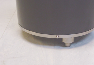
Assuming all the parts are present, stand the seismometer in the centre of a bench and identify its external features:
a handle with North indication,
DATA OUT and GPS connectors;
a mil-spec FireWire connector;
other optional connectors as ordered;
a bubble level,
an air vent port,
two adjustable feet, and
two accurate orientation pins (one brass and one steel).
3.1.2 Serial number
The sensor's serial number can be found on the label stuck to the top lid of the sensor. You should quote this serial number if you need assistance from Güralp Systems.
3.1.3 Handling notes
The 3ESPCD is a sensitive instrument, and is easily damaged if mishandled. If you are at all unsure about the handling or installation of the device, you should contact Güralp Systems for assistance.
Avoid bumping or jolting any part of the sensor when handling or unpacking.
Do not kink or walk on the data cable (especially on rough surfaces such as gravel), nor allow it to bear the weight of the sensor.
Do not connect the instrument to power sources except where instructed.
Do not ground any of the signal lines from the sensor.
Avoid moving the instrument whilst the masses are unlocked. The 3ESPCD is designed to tolerate a certain amount of motion with the sensor masses unlocked, e.g. over short distances carried by hand. For example, if the remote locking procedure fails, removing the instrument for diagnostics is unlikely to damage it. However, you should always lock the sensor masses before shipping or transporting the sensor over longer distances.
3.1.4 Connections
The instrument has the following connectors:
The DATA OUT connector outputs RS232 data to your PC or data module, and also provides power to the instrument.
The GPS connector is intended for connection to a Güralp GPS module.
The FIREWIRE connector can be attached to any IEEE.1394 (FireWire) hard disk or data storage unit using the cable provided.
3.1.5 Power supply
The sensor requires a 12 V power supply, which it obtains through the DATA OUT port. You may wish to terminate the supplied power cable in order to connect a 12 V power source to this connector: it is supplied with bare ends. Using a 12 V, 25 Ah sealed heavy-duty lead-acid battery, you should expect the instrument to operate for around a week without recharging.
A power management module can be installed as an option, which allows the 3ESPCD to operate from a 10 – 15 V supply range. This module also cuts the input power to the sensor electronics if it drops below 10.5 V, to minimize discharge from battery-operated installations.
The 3ESPCD draws a nominal current of 200 mA from a 12 V supply when in use. During locking and unlocking of the sensor masses, this current rises briefly to 750 mA. It is recommended that you carry a spare 12 V battery when visiting an installation for maintenance, in case the sensor needs to be moved and the on-site batteries no longer have sufficient charge to perform the locking procedure.
3.1.6 FireWire
The digitiser has an IEEE.1394 (“FireWire”) port, which you can use to download data onto a compatible hard disk.
Before you can use the disk, you will need to erase/format it. The digitiser saves data on the hard disk in raw mode, so you cannot use a PC's standard software to reset the disk.
To erase/format a FireWire disk for use with the 3ESPCD:
Power up the digitiser, and connect it to your computer's serial port.
Open its terminal console. To do this using Güralp Systems' Scream! software, right-click on the digitiser's icon (once it appears) and select Terminal....
or
From a Güralp EAM, issue the command data-terminal and select the appropriate data source from the menu.
Issue the command DISKMENU. You will see the message
Plug in FireWire cable
Plug in your disk. The digitiser will display information about the disk as soon as it is detected. Within the next seven seconds, press any key to bring up the disk menu.
Key
 to reset the disk.
When the reset is complete, remove the disk.
You will now be able to download data onto the disk when required.
3.2 Installation notes
The goal of any seismic installation is to ensure that wave-trains arriving at the instrument accurately reflect the internal motion of subsurface rock formations. To achieve this, the seismometer and its emplacement need to be considered as a mechanical system, which will have its own vibrational modes and resonances. These frequencies should be raised as high as possible so that they do not interfere with true ground motion: ideally, beyond the range of the instrument.
In particular, the sensor needs to be protected against environmental factors such as
fluctuations in temperature,
turbulent air flow around walls or trees, or around sharp corners or edges in the immediate vicinity of the sensor;
vibration caused by equipment in or near the installation, particularly computer equipment; and
vibration caused by heavy machinery (even at a distance), or by overhead power lines.
In seismic vaults, instruments are often installed on piers. It is important to ensure that the interface between the pier and the floor does not introduce noise, and that the pier itself does not have resonant frequencies within the passband. Ideally, a seismic pier will be significantly wider than it is high (to minimize flexing) and will form a single piece with the floor, e.g. by moulding a poured concrete floor with a wooden frame.
Many situations do not allow for the construction of a seismic vault. For example, you may need to deploy quickly to monitor the activity of a volcano showing signs of rejuvenation, or to study the aftershocks of a major earthquake; or the site itself may be too remote to ship in construction equipment.
Temporary installations can be protected against spurious vibrations by
selecting a suitable site,
placing the instrument in a protective enclosure (an open-sided box of 5 cm expanded polystyrene slabs, placed over the instrument and taped down to exclude draughts, makes an excellent thermal shield),
standing the sensor on bedrock where possible, or at least deep in well-compacted subsoil;
clearing the floor of the hole of all loose material; and
using as little extra mass as possible in preparing the chamber.
After installation, the instrument case and mounting surface will slowly return to the local temperature, and settle in their positions. This will take around four hours from the time installation is completed. If you require long-period recording, you should re-zero the instrument after this time.
3.3 Installing in vaults
You can install a 3ESPCD in an existing seismic vault with the following procedure:
Unpack the sensor from its container, saving the shipping box for later transportation.
Prepare the mounting surface, which should be smooth and free of cracks. Remove any loose particles or dust, and any pieces of loose surfacing. This ensures good contact between the instrument's feet and the surface.
If it is not already present, inscribe an accurate North-South line on the mounting surface.
Place the sensor over the scribed line, so that the brass and steel pointers are aligned with the marked directions, with the brass pointer facing North. This can be done by rotating the base of the sensor whilst observing it from above. The brass pointer can be found next to one of the feet.
If you cannot easily see the pointers, you should align the sensor using the north arrow on the handle. However, the alignment of the handle with the sensors inside is less accurate than the metal pointers, so they should be used wherever possible.
The top panel of the 3ESPCD includes a spirit level.
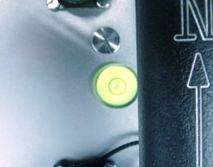
Level the sensor using each of the adjustable feet of the instrument in turn, until the bubble in the spirit level lies entirely within the inner circle. (The instrument can operate with up to 2° of tilt, but with reduced performance.)
The feet are mounted on screw threads. To adjust the height of a foot, turn the brass locking nut anticlockwise to loosen it, and rotate the foot so that it screws either in or out. When you are happy with the height, tighten the brass locking nut clockwise to secure the foot. When locked, the nut should be at the bottom of its travel for optimal noise performance.

Plug the grey/blue power/data cable into the ten-pin connector on the instrument's lid and connect a 12 V power supply to the ends of the grey cable. Connect the DE9 connector to a PC running scream, using a USB-to-RS232 converter, if required.
Note: GSL strongly recommend USB/RS232 convertors based on the FTDI chipset. Numerous problems have been found with convertors based on the other common chip-set.
Alternatively, connect the ten-pin connector on the instrument's lid to a Güralp EAM using cable CAS-DCM-0001 (green).
Plug in the GPS cable and connect the GPS receiver.
In Scream's set-up dialogue, select the “COM Ports” tab and set the Baud rate of the appropriate COM port to 38,400 Baud. Click OK and wait for the instrument to appear in Scream's source tree.
Right-click on the digitiser's entry in the source tree and select Control.... Click on the Mass control tab, followed by Unlock. (If the Mass control tab is unavailable, check the sensor type in the Sensor type tab, apply, and open a new Control window.)
Alternatively, if you are using an EAM, navigate to the Control → Instruments → Port X Instrument... page and click on the Unlock instrument button.
Caution: After this point, you should be careful not to tilt the instrument or you may damage it.
Right-click on the digitiser's entry in Scream's source tree and select Control.... Click on the Mass control tab, followed by Centre.
Alternatively, if you are using an EAM, navigate to the Control → Instruments → Port X Instrument... page and click on the centre button.
Monitor the mass positions during the centring operation. You may need to initiate several rounds of centring before the mass positions reach an acceptable value.
Cover the instrument with thermal insulation, for example, a 5 cm expanded polystyrene box. This will shield it from thermal fluctuations and convection currents in the vault. It also helps to stratify the air in the seismometer package. Position the thermal insulation carefully so that it does not touch the sensor package.
Ensure that the cables are loose and that they exit the seismometer enclosure at the base of the instrument. This will prevent vibrations from being inadvertently transmitted along the cables.
3.4 Installing in pits
For outdoor installations, high-quality results can be obtained by constructing a seismic pit.
Depending on the time and resources available, this type of installation can suit all kinds of deployment, from rapid temporary installations to medium-term telemetered stations.
Ideally, the sensor should rest directly on the bedrock for maximum coupling to surface movements. However, if bedrock cannot be reached, good results can be obtained by placing the sensor on a granite pier on a bed of dry sand.
Prepare a hole of 60 – 90 cm depth to compacted subsoil, or down to the bedrock if possible.
On granite or other hard bedrock, use an angle grinder to plane off the bedrock at the pit bottom so that it is flat and level. Stand the instrument directly on the bedrock, and go to step 7.
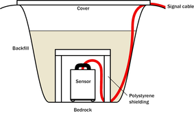
On soft bedrock or subsoil, you should install a pier as depicted below.
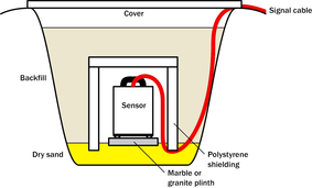
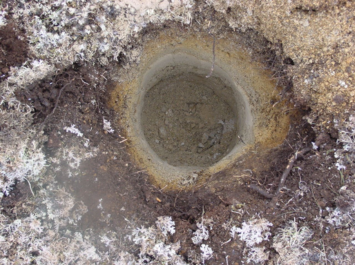
Pour a layer of loose, fine sand into the pit to cover the base. The type of sand used for children's sand-pits is ideal, since the grains are clean, dry and within a small size range. On top of the sand, place a smooth, flat granite plinth around 20 cm across, and shift it to compact the sand and provide a near-level surface.
Placing a granite plinth on a sand layer increases the contact between the ground and the plinth, and improves the performance of the instrument. There is also no need to mix concrete or to wait for it to set, as in step 4.
Alternatively, if time allows and granite is not available, prepare a concrete mix with sand and fine grit, and pour it into the hole. Agitate (“puddle”) it whilst still liquid, to allow it to flow out and form a level surface, then leave to set. Follow on from step 7.
Puddled concrete produces a fine-textured, level floor for emplacing the seismometer. However, once set hard, the concrete does not have the best possible coupling to the subsoil or bedrock, which has some leeway to shift or settle beneath it.
Alternatively, for the most rapid installation, place loose soil over the bottom of the pit, and compact it with a flat stone. Place the seismometer on top of this stone. This method emulates that in step 3, but can be performed on-site with no additional equipment.
Set up the instrument as described in Section 3.3.
The instrument must now be shielded from air currents and temperature fluctuations. This is best done by covering it with a thermal shield.
An open-sided box of 5 cm expanded polystyrene slabs is recommended. If using a seismic plinth on sand (from steps 3–4 or 5), ensure that the box is firmly placed in the sand, without touching the plinth at any point. In other installations, tape the box down to the surface to exclude draughts.
Alternatively, if a box is not available, cover the instrument with fine sand up to the top.
The sand insulates the instrument and protects it from thermal fluctuations, as well as minimizing unwanted vibration.
Ensure that the sensor cable is loose and that it exits the seismometer enclosure at the base of the instrument. This will prevent vibrations from being inadvertently transmitted along the cable.
Cover the pit with a wooden lid, and back-fill with fresh turf.
3.5 Other installation methods
The recommended installation methods have been extensively tested in a wide range of situations. However, past practice in seismometer installation has varied widely.
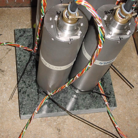
Some installations introduce a layer of ceramic tiles between a rock or concrete plinth and the seismometer, as shown in the left-hand picture below:
However, noise tests show that this method of installation is significantly inferior to the same concrete plinth with the tiles removed (right). Horizontal sensors show shifting due to moisture trapped between the concrete and tiling, whilst the vertical sensors show “pings” as the tile settles.
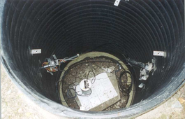
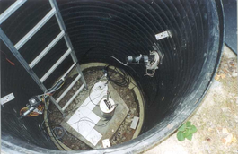
Other installations have been attempted with the instrument encased in plaster of Paris, or some other hard-setting compound (left):
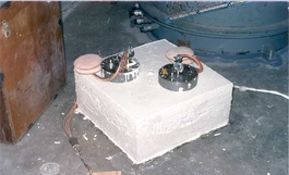
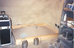
 Again, this method produces inferior bonding to the instrument, and moisture becomes trapped between the hard surfaces. We recommend the use of fine dry sand (right) contained in a box if necessary, which can also insulate the instrument against convection currents and temperature changes. Sand has the further advantage of being very easy to install, requiring no preparation.
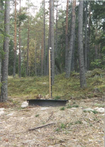
Finally, many pit installations have a large space around the seismometer, covered with a wooden roof. Large air-filled cavities are susceptible to currents which produce lower-frequency vibrations, and sharp edges and corners can give rise to turbulence. We recommend that a wooden box is placed around the sensor to protect it from these currents. The emplacement may then be backfilled with fresh turf to insulate it from vibrations at the surface, or simply roofed as before.
By following these guidelines, you will ensure that your seismic installation is ready to produce the highest quality data.
3.6 Rapid installation
This section details a method of deploying 3ESPCD instruments with the minimum of additional equipment. This is recommended for situations where seismic instrumentation needs to be installed very quickly, e.g. to study a resumption of volcanic activity, or where difficulty of access to the site prevents you from constructing a full seismic pit. You should always construct a pit if possible (see Section 3.4), since the data produced will be of significantly higher quality.
3.6.1 Deployment
Prepare a hole of 60 – 90 cm depth to compacted subsoil, or down to the bedrock if possible.
Clean the hole down to the bottom, and remove any loose material from the mouth. Ensure that the bottom of the hole is relatively flat.
If the bottom of the hole is made of hard rock, you may need to put in some loose sand or soil so that the sensor can be levelled.
Connect the sensor to cables for the GPS unit and power source.
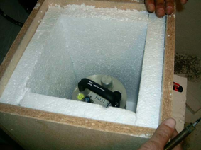
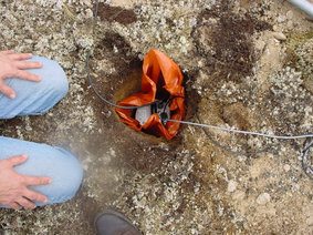
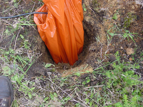
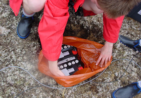
Carefully insert the instrument into the hole, protected by a tough plastic bag to keep water out. Use a bag strong enough to bear the weight of the sensor and breakout box, so that it can be recovered easily.
Press the sensor down firmly into the soil, without tapping or hitting it.
Check the bubble level on top of the instrument package. Adjust the instrument's position if necessary so that the bubble lies entirely within the black circle.
Pack soil or sand around the instrument to hold it steady. Make sure the soil or sand is firmly compacted and not at all loose.
Recheck the bubble level. If you cannot adjust the soil packing at this stage and the sensor is not level, you will need to clear the hole and restart from step 3.
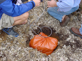
Power the sensor and connect it to a laptop. Unlock the masses using Scream's Control window.
Place the breakout box and any excess cable on top of the sensor, inside the plastic bag.
Group the cables coming from the bag for a distance of about 1 m, and keep them together with insulating tape.
Tie the top of the package and fold it over so that water cannot get in. Leave any excess cable within the bag.
Cover the installation with soil or sand until it is no longer visible.
Attach a GPS unit to the cable coming from the sensor. Seal the connection between the data cable and the GPS unit's IEEE 1394 cable inside a plastic bag to protect it from moisture.
Position the GPS unit so that it has a good view of the sky. Bury the cable and connector package so that they cannot be seen.
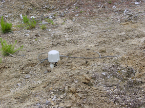
If possible, place the GPS near the instrument so that it can be found more easily, and the connector package near the GPS so you can retrieve data from the instrument without affecting the installation.
If you are using a battery as a power source, dig a second hole for it. This hole does not need to be as deep as the pit for the instrument—perhaps 10 cm plus the height of the battery.
Attach the sensor power cable to the battery, and wrap it in another plastic bag. Place the bag in the hole.
Tie the bag and fold over, to make the battery as waterproof as possible.
Bury the power cable between the battery and the instrument, and compact soil or sand around the bag.
Fill in and cover the hole so that it is not visible.
3.6.2 Recovery
Care should be taken when recovering the 3ESPCD, since tapping or banging it can cause damage to the sensors inside. The following instructions assume that you have installed the instrument following the steps above.
Find the GPS receiver, which will be the only feature visible from the surface, and follow the buried data cable from it to the instrument.
Carefully remove earth from the hole until you find the power cable coming from the instrument.
Follow the power cable to the battery pit, and carefully dig away the soil to reveal the battery about 10 cm from the surface.
Connect a laptop to the data connector and, using Scream's Control dialogue, lock the masses.
Disconnect the power cable from the battery. (With the power off, the sensor is less likely to suffer electrical damage during recovery.)
Return to the location of the sensor, and dig down to it. You should be able to remove a spade's head depth of soil without hitting the instrument. Beyond that, using a small hand shovel, follow the wires and carefully remove the remaining soil until you can see the plastic bag. Take special care not to damage the wires, which should be tied together in the vicinity of the bag.
Carry on removing soil, either with your hands or (very carefully!) with the shovel, until the whole bag is uncovered to about half the height of the instrument.
If the hole is relatively dry, open the bag and lift the instrument out by its handle.
Caution: Do not lift the instrument by any of the attached cables. Straining the cables may result in invisible damage, making future installations unreliable.
Alternatively, if the hole is waterlogged, carefully lift out the entire bag in one piece, and remove the contents at the surface.
3.7 Installing in post-holes
The 3ESPCD is suitable for installation in potholes. In soft subsoil, a hole 2 – 4 metres deep and 20 cm wide can be conveniently excavated using a tractor-mounted or hand-operated pothole auger. To minimize surface effects, you should ensure that the hole is at least 1 metre deeper than the length of the instrument, and preferably somewhat more.
Since the hole has no lining, it may occasionally flood. However, most soil types are sufficiently permeable to allow water to soak away, leaving the packing material moist.
To install a 3ESPCD in a pothole:
Clean the pothole, making sure there is no loose material around the mouth of the hole or on its base.
Prepare the instrument package, making sure the inclinometer is visible, and attach it to a winch or hoist by clamping a light steel cable to the centre of the handle so that the package hangs vertically. Connect the signal cable to the instrument.
Add packing material to the hole to about 15 cm depth. Fine crushed rock, with a high proportion of rock flour and fine particles, makes excellent packing material. Alternatively, a mixture of 3 mm grade angular coarse grit with around 30% medium grit gives good results. Moisten the packing material in the hole and ram firm.
Lower the instrument to the bottom of the hole, but without slackening the lifting cable.
Fill more packing material around the instrument for about 30 cm, moisten, and ram firm.
Use the bubble level to check that the instrument remains within its tilt tolerance (± 2 °).
Continue filling, moistening and packing until the instrument is buried, checking that the tilt remains within tolerance.
Release the strain on the lifting cable, and allow the packing material to settle for 24 hours.
If all is well after the settling period, release the lifting tackle, coil a tail of the lifting wire into the top of the hole and backfill almost to the surface.
Ensure that the signal cable is slack, and fix it to a support at the top of the hole.
Ram a split wooden bung into the top of the hole, and cover with sandbags.
Attach the signal cable to your laptop. Power the sensor, and unlock it. Carry out preliminary tests using Scream!, if required.
3.8 Using the 3ESPCD
Once the 3ESPCD is powered, it will start producing data immediately. You can now start configuring it for your own needs. There are three ways you can do this:
using the graphical interface provided by Scream! (see section 5);
using the web interface of a Güralp EAM (see MAN-EAM-0003); or
over a terminal connection (see section 6).
All three methods provide full access to the configuration options of the digitiser.
3.8.1 Retrieving data
You can configure the digitiser to operate in a number of transmission modes. These modes determine whether the unit stores data in its on-board Flash memory, sends it over the serial link in GCF format, or does some combination of these. See “Data flow ” in Section 5.2.5 for more details.
If you choose a transmission mode where some data are stored in Flash memory, you will need to recover this data at a later date. You can do this either over the serial link, or using the digitiser's FireWire interface.
To download data over FireWire, simply plug the disk in. If there are enough new data waiting to be transferred (by default 128 Mb), they will immediately be downloaded onto the disk. The internal pointers will be updated to mark the data as downloaded.
Alternatively, for more downloading options, issue the command DISKMENU from the digitiser's console before attaching the disk. See Section 6.7 for more information. You can use DISKMENU to download any section of data, whether or not it has already been transferred.
While the FireWire interface is active, it will consume about 200 mA of power (from a 12 V supply). If you interrupt a transfer whilst in progress, the digitiser will re-boot, but the data held in memory will not be affected.
To download data over the serial link:
Open the digitiser's console. To do this using Güralp Systems' Scream! software, right-click on the digitiser's icon (once it appears) and select Terminal....
Alternatively, from a Güralp EAM, issue the command
data-terminal
If you want to download all data held in the Flash memory, issue the command
ALL-FLASH ALL-DATA DOWNLOAD
Alternatively, select a particular set of streams, sample rates and times to download using the STREAM, S/S, FROM-TIME and TO-TIME commands, and finish with DOWNLOAD. See Section 6.7 for more information.
Close the terminal session. If you are using Scream! or an EAM, the digitiser should start transmitting immediately. Otherwise, you may need to issue the command GO to start transferring data.
3.8.2 Reading digitiser disks
The digitiser uses a special disk format, DFD, for recording data. You can read this data into a PC using Scream! or the GCFXtract utility, which is freely available from the Güralp Systems Web site.
Note: The DFD format is not the same as that used by the Güralp Systems EAM data modules, which use a FAT32-compatible or extn journalling file system.
Güralp Systems can provide fully-tested disks with FireWire and USB connectors. Alternatively, a third-party FireWire disk may be used (although compatibility is not guaranteed.)
3.8.2.1 Reading disks with GCFXtract
To read a disk using GCFXtract:
Attach the disk to your computer. You can use FireWire, USB, or any other interface supported by your computer and the disk.
Caution: Some operating systems, not recognising the DFD format, will offer to re-format the disk when it is attached. Always say NO: reformatting the disk will make the recorded data unreachable and may over-write some of it. If you accidentally allow the operating system to format a drive containing valuable recorded seismic data, please contact support@guralp.com for help.
Start GCFXtract
Note: As GCFXtract requires raw disk device access, it must be run with elevated privileges. On Windows 7 and Windows Vista, it needs to “Run as Adminsitrator”. On Windows XP, you need to be logged in as administrator. On Linux, you need to run as root, or a user with read/write permissions for raw disk devices. On most Linux systems, you can grant these permissions with the command
sudo adduser user_name disk
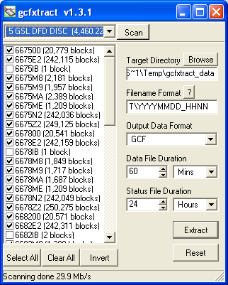
The following screen is displayed:
The program will first search for non-DOS disks on all the interfaces it understands. If it does not find your disk, check that it is properly connected and that any relevant drivers have been installed, then click the
 button.
When you start up GCFXtract, the program searches all SCSI interfaces and devices for DM24-format disk drives. The ID of each disk is displayed in the drop-down list at the top of the window. Under each disk, GCFXtract lists the transfer sessions it has found on the disk. The DM24 creates a new transfer session each time it saves data to the disk. You can extract data either from a single transfer session, or from the entire disk.
Select the required disk or transfer session from the drop-down list, and click
. GCFXtract will scan the disk and display all the streams it finds in the selection area below. For each stream, the Stream ID and the number of blocks found are shown. This operation requires roughly 12 Mb of available memory for every Gb of space on the disk. If you have a very large disk, your computer may have to use its hard disk to make enough space. This will slow down scanning considerably. By default, all streams containing more than 100 blocks are selected for extraction. You can change which streams to extract by ticking or clearing the check-box beside each stream. You can tick or clear all of the boxes using the
 and
and  buttons. Clicking
  ticks all cleared boxes, and clears all ticked boxes.
 Enter a path name into the Target Directory field, or use the
 button to find a directory. This will be used as the root directory for extracted data. If it does not exist, GCFXtract will create it.
 Enter a format string into the Filename Format field. The syntax is the same as the format string in Scream! and full documentation is available by pressing the
 button beside the format entry field in interactive mode.
 Normally, GCFXtract outputs GCF files, to ensure all the information in the original data are retained. If you want to convert to a different format, select it from the Output Data Format drop-down box. GCFXtract can output in most of the formats supported by Scream!.
Data are automatically placed in time order and saved in multiple files, each file containing a contiguous segment of data. By default, data streams are recorded in files 60 minutes long. To change this to some other number of minutes, alter the value in the Data File Duration (mins) box. For data streams, if there is a gap in the data, GCFXtract will start a new file anyway.
Status streams are also saved in multiple files, but have a default length of 24 hours. To change this, alter the value under Status File Duration (hours).
When you are happy with the settings, click
 to begin extracting the data.
 Clicking
 sets a flag on the disk which marks it as empty. Next time a digitiser wants to transfer data, it will begin at the beginning of the disk, overwriting the old data. When this happens, none of the old data can be extracted with GCFXtract. Until then, however, you will still be able to retrieve all the data.
3.8.2.2 Reading disks with Scream!
You can also read disks with Scream!. This allows you to view data in the process of being transferred, but is slightly slower, because Scream! does not read data in strict order. To read a disk with Scream!:
Attach the disk to your computer. You can use FireWire, USB, or any other interface supported by your computer and the disk.
Run Scream!, and select File → Setup... from the main menu. Select the Files tab.
Set the Base Directory, Filename Format and Data Format as required. Also, if required, set the Post-processor and Granularity options to your preference. Consult the Scream! documentation for details.
Select the Recording tab, and tick the Auto Record—Enable for Data Streams and Auto Record—Enable for Status Streams check-boxes. Click OK. Scream! will remember the recording options you set in steps 3 and 4 for later occasions.
Select File → Read SCSI disk... from the main menu. Scream! will search for attached disks, and open a window with a list of all the streams it has found.
Select the streams you want to replay, and click Open. The disk will appear in the left-hand pane of Scream!'s main window, and the streams you have selected will start playing into the stream buffer, as well as being recorded.
When you have finished transferring the data, if you want to reset the disk, select File → Reset SCSI disk... from Scream!'s main menu. Select the disk you want to reset, and click OK.
More information is contained in the Scream! Manual, MAN-SWA-0001.