Chapter 2. Using the DM16
2.1 Connections
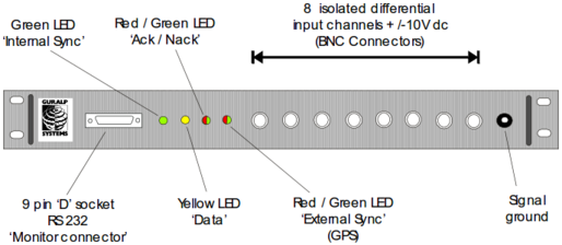
Front panel
Rear panel
Power Connection : Connect supply power (+12 Vdc and 0 Vdc) to the rear connector (Binder series 712) using the cable provided. The pinouts for this cable and connector are given at the back of this guide.
RS-232 Connections : Normally the rear Data connector is duplex, and the front Monitor connector is simplex. For normal operations, connect the rear Data port to the modem, radio, phone line, etc. over which data will be sent, and, if using a 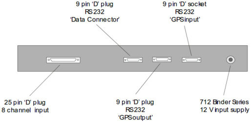 duplex link, over which the digitizer can be remotely configured. To monitor the digitizer’s output locally, connect a laptop PC to the Monitor connector and run SCREAM. To configure the digitizer locally, connect the laptop PC to the front Monitor connector using a specially-wired (pin 4 to pin 1; see pinouts) 9-way male serial plug. Use of the specially-wired plug temporarily disables the rear Data connector, and converts the front Monitor connector to duplex, allowing digitizer configuration and monitoring.
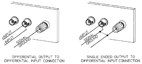
Analog Inputs : Analog inputs (+/- 10Vdc) can be connected to the digitizer via the front BNC connectors or via the rear 25-way connector (see pinouts attached).
Terminate unused input ports on the front panel with a 50 Ω BNC terminator cap, unless the 25 way rear connector is used for signal inputs into the digitizer. If you use the 25-way connector for an input, then the corresponding BNC input on the front must not be terminated.
GPS Receiver : Use the cable provided to connect the GPS receiver (Garmin antenna) to the rear GPS In connector. The DM16/R8 is designed to allow a single GPS receiver to synchronize multiple digitizers. The first digitizer in the chain must have the GPS receiver connected directly to the rear GPS In connector. Subsequent digitizers can be daisy-chained together, using the rear GPS Out and GPS In connectors. Note that each digitizer in the line adds 5.5 microseconds delay to the actual GPS time stamp.
Front panel LEDs
Int Sync (Internal synchronization) : This LED flashes GREEN whenever the digitizer's internal oscillator generates a timing pulse. Should always flash as long as the digitizer is powered.
Data (Data transmission) : This LED flashes YELLOW when a GCF block is sent from the digitizer. The rate of flashing for this LED depends on the configured sampling rate(s). No activity indicates that data is not being sent.
Ack/Nack (Acknowledge/No Acknowledge) : Indicates whether data blocks are being acknowledged by SCREAM (requires duplex link, via serial port).
If LED is off, SCREAM is not attached, or the link to SCREAM is simplex.
GREEN : SCREAM is attached and acknowledging blocks (the LED blinks momentarily for each block received).
RED : a block(s) was not acknowledged.
ExtSync (External synchronization) : The timing pulse from the GPS receiver.
No activity indicates that the GPS receiver is not attached or is inoperative.
RED blink :- indicates GPS is attached and operating, but has not yet obtained a fix.
GREEN blink : at one second intervals, indicates GPS has obtained a fix.
GREEN blink synchronized with IntSync LED: indicates GPS has obtained a fix and the internal oscillator is synchronized to it.
2.2 Quick start
Connect the GPS cable to the digitizer’s plug marked ‘GPS Input’ (GPS is not essential for initial test setup).
Connect the cable from the plug marked ‘Data Output’ to the COM port of a PC.
Install SCREAM software (see later chapter) on your PC and run.
Connect a 12V DC power supply to the DM16-R8 plug marked ‘Power’. (the DM16-R8 will operate from 10 to 36 V DC). At 12 V, the DM16-R8 draws 210-220mA, or 310-320mA with one GPS2 connected
To configure the COM port connected to the digitizer, start from the main window in SCREAM
Click on the ‘File’ button , select ‘Setup’
Select the ‘Com Ports’ tab.
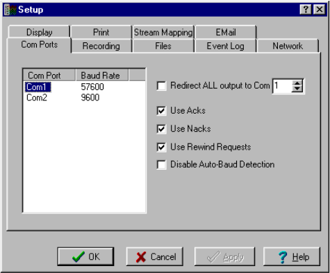
Click on the COM port to which the digitizer is connected.
Select Autodetect from the Baud Rate drop-down menu.
SCREAM will detect, then display the baud rate that the digitizers output is currently set at.
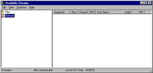
Click OK to return to the main Available Streams window.
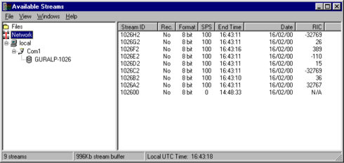
In the Available Streams window the identifier of the digitizer will appear in the left hand frame. The data streams will appear in the righthand frame.
The Stream ID’s are six character strings uniquely identifying each instrument, component and sample rate. (There may be upto three different sample rates per channel)
The stream ending in ‘00’ contains status information from the digitizer.
Analogue signals can now be connected to any of the eight individual differential inputs on the front of the digitizer or via the 25 pin ‘D’plug on the rear of the unit.
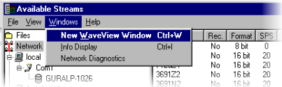
From the main ‘Available Streams’ window, choose Windows – New WaveView Window.
Select the data streams and drag them into the WaveView window.
To see status information coming from the digitizer, right click on the status stream, from the pop-up menu select ‘View’. A new window, ‘Status’ should open containing text. The first blocks will give the boot message from the DM. Later blocks give information on the expected GPS satellites, the location of the GPS antenna, time synchronization status and transmit and receive baud rates for each channel and the data link.