Chapter 2. Connections
2.1 Front panel
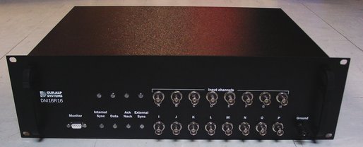
The front panel has the following features, from left to right:
Monitor : This is a 9-way “D”-type plug which connects to a serial port on the DCM. As supplied, this port is set to the getty service which allows you to access the DCM's console. When you first set up the unit, you should connect to this port to assign the DCM an IP address and perform initial configuration. See the DCM manual for full details.
The Monitor plug is connected directly to the DCM console plug on the back panel. Because of this, you cannot connect to both plugs at the same time. Doing so may damage the DM16 or your computer's serial port.
To the right of the Monitor plug are 8 LED indicators. These form four pairs labelled Internal Sync, Data, Ack/Nack and External Sync. The top LED of each pair reflects the status of the first internal digitizer, which controls channels A – H The bottom LED of each pair reflects the status of the second internal digitizer, which controls channels I – P.
Internal Sync : This LED blinks green when its internal oscillator generates a timing pulse. It should blink continuously whilst the unit is powered.
Data : This LED blinks yellow when a data block is output from the digitizer. Using higher sampling rates will make it blink more rapidly.
Ack/Nack : Under normal conditions, this LED show the status of the internal link between the digitizer and the DCM. It blinks green when a data block from the digitizer is acknowledged by the DCM, and red if a “not acknowledged” message is received.
If you connect a computer to the Data Out plug (see below) from one of the digitizers, the computer takes control of the digitizer from the DCM. The Ack/Nack LED for that digitizer will now blink when a data block is acknowledged (or “not acknowledged”) by the computer. The DCM will still be able to receive data.
External Sync : This LED blinks when the digitizer receives a GPS timing pulse. A green colour means that the GPS is operating, but the digitizer is not yet synchronised to it. When the digitizer successfully synchronises, the LED will turn red.
Input Channels : These plugs should be connected to your analogue equipment. They have an input range of ±10 V.
Either differential or single-ended signal sources can be used. If you are using a single-ended signal source, you should connect the outer part of the BNC connector to the ground line as shown.
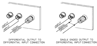
If you are not using an input channel, you should terminate the plug with a 50 Ω BNC terminator cap. If you are providing input to the channel on the Input Channels “D”-type connector on the rear panel (see below), leave the plug unconnected and unterminated.
Ground : This connector should be securely wired to an earth rod or other stable ground.
2.2 Rear panel
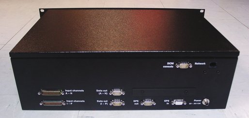
The connectors on this panel are in three rows.
Connections to the DCM (DCM console and Network) are located at the top of the panel.
Connections to the first internal digitizer (channels A – H) are located in the next row.
Connections to the second internal digitizer (channels I – P) are located in the bottom row.
The GPS out and GPS in connectors in the bottom row are shared between the two internal digitizers.
The Power connector in the bottom row is shared between all the internal modules.
The rear panel connectors are, from left to right:
Input channels A –H : This 26-pin “D”-type plug provides alternative connections for the first digitizer. If you connect a signal source to input pins on this connector, do not connect anything to the corresponding input port on the front panel.
Input channels I – P : Alternative connections for the second digitizer. Again, do not connect both front and back panel connectors to signal sources.
Data out (A – H) : This is a standard RS232 serial plug which provides direct access to the first internal digitizer's output. Connecting this to a PC allows you to monitor data from the digitizer for diagnostic purposes. The default baud rate is 38400 baud.
When you connect a computer to the Data out port from a digitizer, the DCM will switch to simplex mode. You can now connect directly to the digitizer from your computer, to configure it or issue terminal commands. However, whilst the computer is connected, you cannot connect to the digitizer through the internal DCM or over the network, although network clients will continue to receive data.
Disconnecting this port returns control of the digitizer to the DCM.
Data out (I – P) : This plug allows you to monitor the second internal digitizer, as for Data out (A – H). Connecting this plug temporarily transfers control of the digitizer to your computer, as above.
GPS out : This port provides a pass-through connection to the GPS receiver connected to the GPS in port.
GPS in : This port should be connected to a suitable GPS receiver which supports the NMEA standard, such as the Güralp Systems CMG-GPS2. It is connected to both digitizers and to the GPS out port, above.
DCM console : This is a full-duplex RS232 port which provides access to the DCM's Data Out port. By default, the DCM has this port set to the getty service, allowing you to connect to the DCM's console and issue commands.
This port is directly wired to the Monitor port on the front panel. Because of this, you cannot connect to both plugs at the same time. Doing so may damage the DM16 or your computer's serial port.
Power 10 – 36 V DC : This single connector provides power to all the internal components. Any suitable DC power source can be used. Adapters for mains (outlet) power are available from Güralp Systems.
Network : This is a standard 10BaseT Ethernet port which can be connected to a hub or switch for your local area network, or direct to a PC with a “cross-over” Ethernet cable. It is wired directly to the Network port on the DCM.