Chapter 7. Configuring digitizers
To configure a digitizer, open the Configuration – Serial Ports page and find the entry for the serial port attached to the digitizer.
Click the Configure – Digitizer link to the right of this entry.
Alternatively, click the same link in the serial port table shown on the front (Summary) page.

This page allows you to set up Güralp instruments attached to any of the DCM's serial ports.
Assuming that the DCM has detected an instrument, its current configuration is now shown on the right side of the page for reference. In the centre of the page, the settings are repeated in a form that you can change. Once you have finished making changes, click Configure instrument. The DCM will then attempt to alter the settings on the digitizer to reflect your choices; this done, you should see the message New configuration successfully saved to attached instrument.
If the DCM is connected to a PC running Güralp Systems' Scream! software, you can also configure the digitizers from within Scream!. See the User Guide for your digitizer model for more details.
7.1 General digitizer settings
Baud rate : The speed at which the digitizer will communicate with the DCM, in bytes per second. This must match the baud rate the DCM is using for the serial port linked to this digitizer. The DCM's baud rates can be altered on the various Serial port configuration pages: see Section 6.2, page 82.
You should ensure that the baud rate is high enough to allow all the data to be transmitted at the rates you have chosen. As an example, for three streams transmitting at 100 Hz, a rate of 9600 baud is usually sufficient. Modern modems can normally operate at rates up to 57600 baud (~56 kbits/s), although the telephone or transmission lines may not support such a high rate. The same is true of radio telemetry links.
System ID and serial number : Together, these two fields uniquely identify data originating from a particular instrument.
Every data or status block sent by the digitizer will contain them as the first two 32-bit fields in the header.
On delivery of the digitizer from the factory, the System ID is set to the Güralp Systems works order number, and the Serial number is set to the serial number for that digitizer.
You can set the System ID to any combination of up to 5 letters (A – Z) and numbers. The Serial number can be up to 4 characters long, also using letters and numbers only. For example, you may wish to set the System ID to a more easily-recognised value, such as an abbreviation of your institution's name.
Sensor type : If the sensor attached to the digitizer is a Güralp velocity sensor, mass control functions (such as sensor locking, unlocking and centering) may be performed through the digitizer and DCM.
Different types of sensor have different functions available. This field allows you to change the type announced by the digitizer.
Timing source : The digitizer needs to be able to time-stamp accurately all data that passes through it. It can set its clock either by receiving time signals from the GPS satellite network using an attached Garmin GPS unit, or by taking time information from a central site via the DCM (stream sync mode). In stream sync mode, the digitizer expects to receive GCF packets from the central timing source (which may have its own GPS unit, or take signals from one of the radio time standards). The DCM can recognise GCF timing packets and will pass them on to all connected digitizers.
GPS Power Cycle : If you have selected Garmin GPS as the timing source, above, this setting determines how often the attached instrument will power up the GPS receiver to obtain an accurate timing signal. Between timing fixes the instrument will run on its internal clock, saving power at a small expense in accuracy. If your instrument has ready access to a power source, you should select always on.
7.2 Digitizer output control
The analogue-to-digital converters on a DM24 output data sampled at 2000 Hz, which is then filtered and reduced to a lower rate (decimated) using an on-board digital signal processing (DSP) unit. The DSP has four filtering-decimation stages, which run one after the other. Each can be programmed to reduce the sampling rate by a factor between 1 and 10. The output of each stage is called a tap.
Each of the taps may be configured for a different decimation factor by choosing values from the drop-down menus on the left. If you are using a mouse wheel to select values from a drop-down menu, ensure you remove the focus from the drop-down menu before scrolling the window, or you may inadvertently change the setting.
Not all digitizers support the full range of taps and decimation factors. For example, the Güralp DM24 allows you to select decimation factors of 2, 4, 5, 8, and 10 only, and does not allow the decimation factor of Tap 0 to be altered from its default setting of 10. In addition, no combination of decimation factors may be used which produces a non-integer data rate (in Hz). A full list of possible tap combinations for the DM24 is given in Section 7.3, below.
To the right of each decimation factor menu is a grid of six check-boxes marked Z, N, and E. These boxes mark which streams of data to record at each sample rate. Three streams of data are measured by the seismometer, corresponding to movement along each of three perpendicular axes. Although all the streams are decimated by the same set of successive scale factors, you can decide at which stage(s) of processing each stream outputs data. A tick in one of the check boxes will produce an output for a particular channel (column) at the corresponding sample rate (grid).
Each grid also has two rows, which differentiate between constant and triggered output. If a box in the upper row is ticked, that stream will produce output constantly at the corresponding sample rate. If the box below it is ticked, that stream will only produce output at that rate if a particular set of trigger criteria are also met. If the constant-output check box is ticked, the other will be ignored.
The table to the right shows the current setting of the digitizer.
For example:
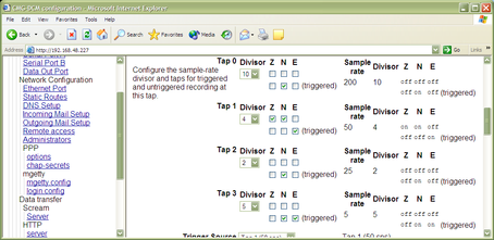
In this example, under normal conditions,
the Z and N data streams will be output by Tap 1 at a rate of 2000/10/4 = 50 Hz, and
the E data stream will not be output.
Additionally, when the trigger criteria are met,
the N data stream will be output by Taps 0, 2 and 3 at rates of 2000/10 = 200 Hz, 2000/10/4/2 = 25 Hz and 2000/10/4/2/5 = 5 Hz, and
the E data stream will be output by Taps 1 and 3 at rates of 2000/10/4 = 50 Hz and 2000/10/4/2/5 = 5 Hz.
The next section allows you to alter the criteria that the digitizer uses when deciding whether a trigger event has occurred.
7.3 Trigger criteria
The triggering algorithm applies a simple short-term average / long-term average calculation to the triggering stream. It works by identifying sections of an incoming data stream when the signal amplitude increases. The purpose of taking a short term average, rather than triggering on signal amplitude directly, is to make it less likely that spurious spikes will trigger the device. Averaging also introduces an element of frequency selectivity into the triggering process.
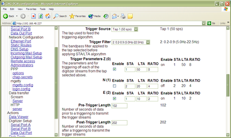
You can select which tap is tested for the trigger from the Trigger source drop-down menu. The tap does not have to be selected for data output for you to be able to use it here.
The next option, Trigger filter, allows you to apply a bandpass filter at this stage (see below.)
Any or all of the channels available at the tap you have selected may be used to determine a trigger. The next part of the window lists the channels, each with Enable, STA, LTA and Ratio settings. The Enable boxes determine which channels are considered for triggering. If any of the checked channels passes the trigger condition, the trigger will activate, and will not detrigger until all of the checked channels have fallen below their respective Ratio values.
The STA and LTA columns allow you to set the intervals over which the two averages are calculated, in seconds. Typically, the time interval for the short term average should be about as long as the signals you want to trigger on, while the long term average should be taken over a much longer interval. Both the STA and LTA values are recalculated continually, even during a trigger.
The Ratio column determines by what factor the STA and LTA must differ for the trigger to be passed. Finding the ratio most suited to your needs is best done by experiment. Too high a value will result in events being missed, while too low a value will result in spurious non-seismic noise triggering the system. Like the averages, their ratio is continuously recalculated for all components. Note that none of the boxes are allowed to be empty, and so you will need to enter the new value before removing the old one. Alternatively, you can use the up and down cursor keys to change the values.
For example, setting the STA to 1 second, the LTA to 10 seconds and the Ratio to 4 would give rise to the following trigger behaviour:
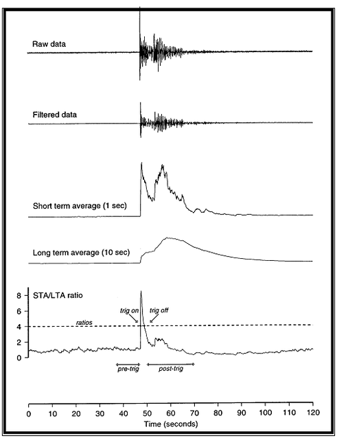
Usually, the values of the STA and LTA periods, and of the Ratio, will be the same for all checked channels. For convenience, Scream! will automatically fill in other values to match ones you enter. If you want to use different values for some channels, you should uncheck Common values before altering them.
If you are using Scream!, you can use the Control window to change the values of the STA and LTA periods, together with the Ratio, without restarting the digitizer. See the documentation for Scream! for more details.
Since it is not generally advisable to trigger from broadband data, the digitizer provides a set of standard bandpass filters to apply to the data streams before they are tested for the trigger condition. This filtering serves to maximise sensitivity within a the frequency band of interest, and filter out noise outside this band. You can select which bandpass filter to use from the Trigger filter drop-down menu. The corner frequencies of the pass band of the filter are determined by the Nyquist frequency, which is given by the sampling rate of the triggering data. The three filter options have pass bands between 10 % and 90 %, between 20 % and 90 % and between 50% and 90% of the data’s Nyquist frequency, respectively.
The possible filter configurations are shown in the following table:
Tap # | Rate (samples/s) | Bandwidth 1 (Hz) | Bandwidth 2 (Hz) | Bandwidth 5 (Hz) |
0 | 200 | 10 – 90 | 20 – 90 | 50 – 90 |
1 | 100 | 5 – 45 | 10 – 45 | 25 – 45 |
| 50 | 2.5 – 22.5 | 5 – 22.5 | 12.5 – 22.5 |
| 40 | 2 – 18 | 4 – 18 | 10 – 18 |
| 25 | 1.25 – 11.25 | 2.5 – 11.25 | 6.25 – 11.25 |
| 20 | 1 – 9 | 2 – 9 | 5 – 9 |
2 | 50 | 2.5 – 22.5 | 5 – 22.5 | 12.5 – 22.5 |
| 25 | 1.25 – 11.25 | 2.5 – 11.25 | 6.25 – 11.25 |
| 20 | 1 – 9 | 2 – 9 | 5 – 9 |
| 10 | 0.5 – 4.5 | 1 – 4.5 | 2.5 – 4.5 |
| 8 | 0.4 – 3.6 | 0.8 – 3.6 | 2 – 3.6 |
| 5 | 0.25 – 2.25 | 0.5 – 2.25 | 1.25 – 2.25 |
| 4 | 0.2 – 1.8 | 0.4 – 1.8 | 1 – 1.8 |
| 2 | 0.1 – 0.9 | 0.2 – 0.9 | 0.5 – 0.9 |
3 | 25 | 1.25 – 11.25 | 12.5 – 11.25 | 6.25 – 11.25 |
| 10 | 0.5 – 4.5 | 1 – 4.5 | 2.5 – 4.5 |
| 5 | 0.25 – 2.25 | 0.5 – 2.25 | 1.25 – 2.25 |
| 4 | 0.2 – 1.8 | 0.4 – 1.8 | 1 – 1.8 |
| 2 | 0.1 – 0.9 | 0.2 – 0.9 | 0.5 – 0.9 |
| 1 | 0.05 – 0.45 | 0.1 – 0.45 | 0.25 – 0.45 |
As can be seen, the filter you choose defines the set of permissible sample rates.
7.4 Auxiliary (“Mux”) channels
Güralp digitizers provide a range of slow-rate auxiliary channels for reporting the system's state of health and other diagnostic information, known as multiplexed (“Mux”) channels. The number of Mux channels depends on the model and configuration of your digitizer. Generally, three channels are used to report the sensor mass position, and another measures the internal temperature of the digitizer. In addition to these, up to 12 Mux channels may be supplied for the user's own purposes. Some digitizers have a separate AUXILIARY port which can be used to access these channels.
You can choose which, if any, of these channels should be transmitted to the DCM in the next section of the page. If one of the check-boxes is ticked, the digitizer will output data on that channel to the DCM, which will then store or transmit it with the rest of the data, according to the way it is configured.
Since it is an optional feature, the digitizer may not use the Pressure Mux channel to report pressure data. If this is the case, that channel may be used for another purpose. Likewise, the three channels marked Spare may not be used, depending on the optional features present in the instrument.
For more information on the format of data packets transmitted on the Mux channels, please refer to the documentation supplied with your digitizer.
7.5 Sensor mass control
There are three commands which can be relayed to an instrument through the DCM to control the position of its sensor mass. For each instrument the buttons which perform these commands (Centre instrument, Lock instrument, and Unlock instrument) can be found at the bottom of the Digitizer Setup page. The type of sensor you have installed determines which, if any, of these commands have any effect.
The CMG-40T sensor type has no mass lock or centring capabilities, so all three buttons are inactive.
The CMG-3ESP sensor type has manual mass lock and remote centring, so only the Centre instrument button is active.
The CMG-3T sensor type is an automated analogue instrument, with all three commands available.
The CMG-3TD sensor type is a fully digital borehole instrument, with all three commands available.
Lock and Unlock instrument are provided so that you can secure the seismometer's sensor mass for safe transportation. Once installed and unlocked, you should Centre instrument to move the mass to the correct position to start measuring data. During the execution of any of these commands, the system will display the three components of the mass's current position and update them once per second per component. When the masses are correctly centered all three readings should be less than ±1,000 counts. Locking or unlocking the sensor mass typically takes several minutes to complete.