Chapter 16. Appendices
16.1 Appendix A - Setting the System Identity (Hostname)
The system identity is pre-set at the factory to contain a device-type identifier and the system's serial number, such as “EAM2010”. It should not be necessary to change this but, should you desire to, the following procedure can be used.
To set the system identity using the web interface select:
Configuration → Hostname
or
Configuration → All options → System identity (hostname)
To set the system identity from the command line, start gconfig and select “System identity (hostname)” from the top level menu.
The following screen is displayed:
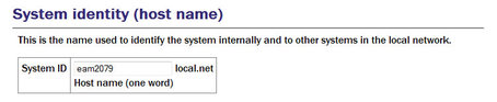
Use this screen to set the hostname of the system.
16.2 Appendix B - Using third-party terminal emulators
There are a number of terminal emulator programs that you can use to access the serial ports of the digitiser and the optional networking interface. The terminal emulator built into Scream is recommended but, if this is not available, there are a variety of alternatives. Three of these are detailed below.
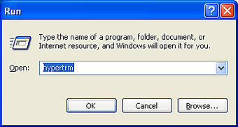
16.2.1 Hyperterminal, as provided with Windows XP.
Click on Start and then Run.
Enter 'hypertrm' and click on
 .
.
The program will ask you for a name for the connection:
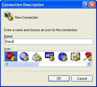
Enter any suitable name, then click
.You will then be prompted to enter COM port and modem details:
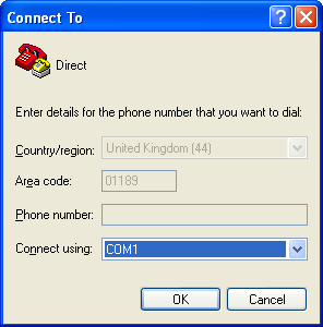
The Country/region, Area code and Phone number fields can be ignored: they are only used when working with modem connections. Select the name of the correct COM port from the Connect using drop-down menu, then click
.Enter the port configuration settings:
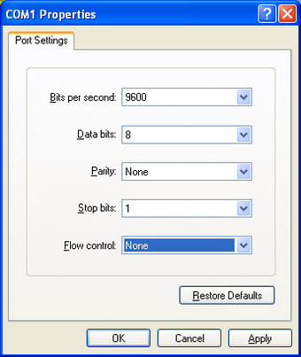
Ensure the following parameters are set:
Bits per second: 38400 for DM24, 115200 for DCM, 19200 for CD24
Data bits: 8
Parity: None
Stop bits: 1
Flow control: None
Caution: If the port is re-configured or the settings changed, access may no longer be possible.
Click on
and the program will then connect, providing you with a terminal emulator screen, from which you can access the command line of your system.
16.2.2 Using Hyperterminal with Windows Vista or Windows 7.
HyperTerminal is not provided with the Windows Vista or Windows 7 operating systems but the necessary files can copied from the i386 directory of the Windows XP CD, if you have one available. The two files you will need are:
hypertrm.dll
hypertrm.exe.
To use Hyperterminal with Windows Vista or Windows 7:
Copy the two files into your windows/system32 directory.
To access HyperTerminal, use Windows+R on your keyboard. Enter 'hypertrm' and click on OK.
If Windows open a security warning window click on Run. You may also be asked if you wish to use HyperTerminal as a the default terminal window.
Now follow the instructions given in section 16.2.1, above.
16.2.3 Using PuTTY for Windows
PuTTY is a free terminal package for windows which is useful if HyperTerminal is not available. It can be downloaded from www.chiark.greenend.org.uk. The easiest package to use is the 'windows installer'. Install PuTTY by following the on-screen instructions.
Start PuTTY by clicking on the desktop icon or Start-menu entry
Click on Serial at the bottom of the category menu on the left:
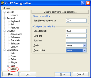
Select a serial line to connect to. This is usually COM1.
Configure the serial line with the following settings:
Speed (baud): 38400 for DM24, 115200 for DCM, 19200 for CD24
Data bits: 8
Stop bits: 1
Parity: None
Flow control: None
Caution: If the port is re-configured or the settings changed, access may no longer be possible.
Click on Session in the main menu.
In the right hand part of the window use the radio buttons to select the Serial Connection type. Check the Serial line and Speed fields are correct.
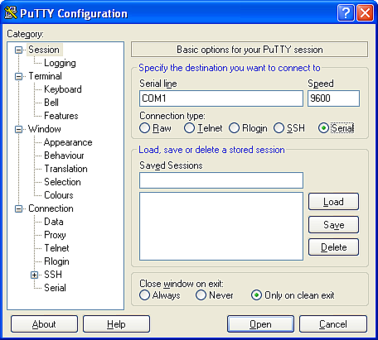
To save the settings enter a suitable session name in the Saved Sessions field then click Save.
The next time you start PuTTY, your saved session will appear in the list and you can simply double-click it to open a new session with the same settings.
Click the Open button to start the terminal emulator.
16.2.4 Mincom for Linux
Under Unix or Linux, Miquel van Smoorenburg's minicom terminal emulator (more details from http://alioth.debian.org/projects/minicom) is recommended, although most terminal emulators can be used. An extract from Minicom's user manual is reproduced in section 16.3.
16.3 Appendix C - Using Minicom
The acquisition module includes the Linux program minicom as a terminal emulator for use with serial devices, including Güralp digitisers. The following is part of the minicom man page.
Minicom is window based. To pop up a window with the function you want, hold the  key while typing
  (from now on, we will use + to denote this), and then the function key (a-z or A-Z). By pressing + first and then
  , a help screen comes up with a short summary of all commands.
For every menu the following keys can be used:
Key | Action |
| UP |
| DOWN |
| LEFT |
| RIGHT |
| CHOOSE |
| CANCEL |
 or
or 
 or
or 
 or
or 
 or
or 


The screen is divided into two portions: the upper 24 lines are the terminal-emulator screen. In this window, ANSI or VT100 escape sequences are interpreted. If there is a line left at the bottom, a status line is placed there. If this is not possible the status line will be showed every time you press +. On terminals that have a special status line, it will be used if the termcap information is complete and the -k flag has been given. Possible commands are listed next, in alphabetical order.
Key | Action |
| Pressing |
| Toggle 'Add Linefeed' on/off. If it is on, a linefeed is added before every carriage return displayed on the screen. |
| Gives you a scroll back buffer. You can scroll up with |
| Clears the screen. |
| Toggle local echo on and off. |
| A break signal is sent. |
| Toggle the type of escape sequence that the cursor keys send between normal and applications mode. (See also the comment about the status line below). |
| Jump to a shell. On return, the whole screen will be redrawn. |
| Clears the screen, runs kermit and redraws the screen upon return. |
| Turn Capture file on off. If turned on, all output sent to the screen will be captured in the file too. |
| Configure minicom. Puts you in the configuration menu. |
| Communication Parameters. Allows you to change the bps rate, parity and number of bits. |
| Exit minicom without resetting the modem. If macros changed and were not saved, you will have a chance to do so. |
| Receive files. Choose from various protocols (external). If you have the filename selection window and the prompt for download directory enabled, you'll get a selection window for choosing the directory for downloading. Otherwise the download directory defined in the Filenames and paths menu will be used. |
| Send files. Choose the protocol like you do with the receive command. If you don't have the file-name selection window enabled (in the File transfer protocols menu), you'll just have to write the file-name(s) in a dialog window. If you have the selection window enabled, a window will pop up showing the file-names in your upload directory. You can tag and un-tag file-names by pressing |
| Choose Terminal emulation: Ansi(color) or vt100. You can also change the backspace key here, turn the status line on or off, and define delay (in milliseconds) after each newline if you need that. |
| Toggle line-wrap on/off. |
| Exit minicom, reset modem. If macros changed and were not saved, you will have a chance to do so. |
| Paste a file. Reads a file and sends its contents just as if it would be typed in. |
| Pop up the help screen. |

 , down with
  , a page up with
  and, if you have them, the
 keys can also be used. You can search for text in the buffer with
  (case-sensitive) or
  +
+ will find the next occurrence of the string.
  will enter citation mode. A text cursor appears and you specify the start line by hitting


 , and move the cursor up and down with


16.4 Appendix D - Troubleshooting
This section of the manual comprises answers to the questions most frequently asked of our support team.
16.4.1 Upgrades report “Temporary failure in name resolution”
If an attempt to run the upgrade process produces error messages like
rsync: getaddrinfo: rsync.guralp.com 873: Temporary failure in name resolution
rsync error: error in socket IO (code 10) at clientserver.c(122) [receiver=3.0.2]
the Domain Name Service (DNS) client is misconfigured. If you are running DHCP, this may be a problem with your DHCP server not providing a nameserver (or providing an incorrect one). If you are using static addressing, check and correct the
16.4.2 Upgrades report “Network is unreachable”
If an attempt to run the upgrade process produces error messages like
rsync: failed to connect to rsync.guralp.com: Network is unreachable (101)
rsync error: error in socket IO (code 10) at clientserver.c(122) [receiver=3.0.2]
the network routing is misconfigured. If you are running DHCP, this may be a problem with your DHCP server not providing a default route (or providing an incorrect one). If you are using static addressing, check and correct the Default route (gateway) field in the “Network interface” configuration page, as described in section 7.1.1.
16.4.3 Upgrades report “rsync error”
If an attempt to run the upgrade process (using the GSL rsync server over the internet) produces error messages like
rsync error: received SIGINT, SIGTERM or SIGHUP (code 20) at rsync.c(541)
the likelihood is that a firewall is blocking traffic on the rsync port. Ask your network administrator to permit the EAM to open TCP connections to host rsync.guralp.com on port 873.
16.4.4 Errors during upgrade: “directory not empty”
This message can occur under two separate sets of circumstances.
On CMG-DCMs running firmware earlier than Build 3696, this message could appear in relation to files with the .so extension and/or files in the /usr/share/terminfo directory. Such units should have their firmware upgraded twice to the latest version. The first upgrade installs a new upgrade script and the second upgrade runs the new script, which fixes this problem.
In all other cases, this message signifies nothing of concern and can be safely ignored.
16.4.5 Upgrade completes but build version remains at 3801
Build 3801 was the last Platinum build that used the OABI software architecture. Subsequent versions use EABI. The two software architectures are not compatible so the standard upgrade method cannot be used to move from build 3801 (or earlier) to the current build. Performing a standard upgrade on a system running build 3801 will check and repair any corrupt files but will not install the latest firmware.
An extra step is required to install the latest firmware. This is fully described in section 5.1. Once you have performed this step, subsequent upgrades will behave as expected.
16.4.6 Regaining access when “locked out”
It is, on some units, possible to configure the network and serial ports in such a way as to make reconfiguration apparently impossible. This section provides directions for regaining control of such units.
On cylindrical digitisers and instruments with integrated DAS, such as the CMG-5TDE, the GPIO connector provides a dedicated serial console (running at 38,400 Baud) which cannot be reconfigured. The GPIO connector on these units can, therefore, always be used to achieve command-line access.
On peli-cased acquisition modules, the 9-pin 'D'-connector under the lid is intended as a dedicated console connector and is preconfigured to run at 38,400 Baud. It is recommended that the port is not reconfigured for other purposes but there is nothing in the firmware to prevent this, so it is still possible to inadvertently mis-configure the system.
There are two common reasons why one might not be able to use a serial port: incorrect port function and incorrect baud rate. This section may help in recovering from these situations.
Connect to the EAM via a serial port, open a terminal emulator (not Scream) and observe the traffic appearing in the window.
Carry out the appropriate procedures depending on the traffic:
16.4.6.1 Short repeated bursts of traffic
If you see a constant stream of unreadable traffic it is likely that the output is set to GCF.
Connect the serial port to a PC running Scream and navigate to File > Setup. Select the 'COM Ports' tab and use 'Auto Detect' from the baud rate drop down menu. Allow Scream to determine the baud rate and note the value that it uses.
Close Scream and start your terminal emulator. Configure it to the baud rate noted in the previous step using the appropriate commands.
Interrupt the GCF data stream by quickly typing:
forcegetty
It may take several attempts for this to succeed. It can be quicker to copy the command from a text editor and repeatedly paste it into the terminal window.
When the interrupt is accepted, the the login prompt will appear.
Login to the EAM as normal and then enter the command:
gconfig
You can now configure the EAM as required.
16.4.6.2 A single burst of traffic
If you see a short burst of unreadable traffic and no password prompt it is likely that the baud rate is wrong.
Change the baud rate using the appropriate commands for your terminal emulator. Try each plausible baud rate in turn.
At each speed, press Enter a few times in the terminal window until the login prompt appears.
Login to the EAM and enter the command:
gconfig
You can now configure the EAM as required.
16.4.6.3 No output and connection not possible
If there is no output at all and you are unable to connect to the EAM, please contact Güralp Systems for assistance.
16.5 Appendix E - Connector pinouts
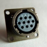
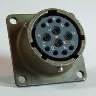
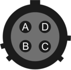
16.5.1 Peli-case: PORTs A, B, C....
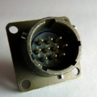
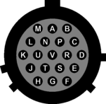
These are standard 10-pin “mil-spec” sockets, conforming to MIL-DTL-26482 (formerly MIL-C-26482). A typical part-number is 02E-12-10S although the initial “02E” varies with manufacturer. Suitable mating connectors have part-numbers like ***-12-10P and are available from Amphenol, ITT Cannon and other manufacturers. |
|
The pin-out is such that the port can be connected to the serial output of a DM24 digitizer using a straight-through cable.
Pin | Function |
A | Power 0 V |
B | Power input +10 to +35VDC |
C | RS232 RTS |
D | RS232 CTS |
E | RS232 DTR |
F | RS232 DSR |
G | RS232 ground |
H | RS232 CD |
J | RS232 transmit |
K | RS232 receive |
| Wiring details for the compatible plug, ***-12-10P, as seen from the cable end (i.e. during assembly). |

16.5.2 Peli-case: Data Out port
This is a standard 10-pin “mil-spec” plug, conforming to MIL-DTL-26482 (formerly MIL-C-26482). A typical part-number is 02E-12-10P although the initial “02E” varies with manufacturer. Suitable mating connectors have part-numbers like ***-12-10S and are available from Amphenol, ITT Cannon and other manufacturers. |
|
The pin-out is the same as the serial output of a DM24 digitizer, allowing you to insert a acquisition module into a pre-existing installation and maintain connectivity.
Pin | Function |
A | Power input, 0 V |
B | Power input +10 to +35VDC |
C | RS232 RTS |
D | RS232 CTS |
E | RS232 DTR |
F | RS232 DSR |
G | RS232 ground |
H | RS232 CD |
J | RS232 receive |
K | RS232 transmit |
| Wiring details for the compatible socket, ***-12-10S, as seen from the cable end (i.e. during assembly). |

16.5.3 Peli-case: USB
This is a standar d 6-pin “mil-spec” socket, conforming to MIL-DTL-26482 (formerly MIL-C-26482). A typical part-number is 02E-10-06S although the initial “02E” varies with manufacturer. Suitable mating connectors have part-numbers like ***-10-06P and are available from Amphenol, ITT Cannon and other manufacturers. |
|
Pin | Function |
A | +5 V DC (USB Type A pin 1) |
B | Data –ve (USB Type A pin 2) |
C | Data +ve (USB Type A pin 3) |
D | 0 V (USB Type A pin 4) |
E | Shielding |
F | not connected |
| Wiring details for the compatible plug, ***-10-06P, as seen from the cable end (i.e. during assembly). |
16.5.4 Peli-case: Network
This is a standard 6-pin “mil-spec” plug, conforming to MIL-DTL-26482 (formerly MIL-C-26482). A typical part-number is 02E-10-06P although the initial “02E” varies with manufacturer. Suitable mating connectors have part-numbers like ***-10-06S and are available from Amphenol, ITT Cannon and other manufacturers. |
|
Pin | Function |
A | not connected |
B | Data transmit +ve (RJ45 pin 1) |
C | Data receive +ve (RJ45 pin 3) |
D | not connected |
E | Data receive –ve (RJ45 pin 6) |
F | Data transmit –ve (RJ45 pin 2) |
| Wiring details for the compatible socket, ***-10-06S, as seen from the cable end (i.e. during assembly). |

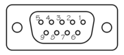
16.5.5 Peli-case: Console
This is a standard DE9F (TIA-574) sub-miniature (D-sub) line socket, conforming to DIN 41652 and MIL-DTL-24308. They are very widely available, as are suitable mating connectors. |
|

The console port is pre-configured to run at 38,400 Baud with 8 data bits, no parity bit and one stop bit. It is strongly recommended that these settings are never changed, so that access to the configuration system can be gained via this port if all other routes are unavailable.
Pin | Function |
1 | not connected |
2 | RS232 transmitted data |
3 | RS232 received data |
4 | not connected |
5 | Ground |
6 | not connected |
7 | not connected |
8 | not connected |
9 | not connected |
| Wiring details for the compatible plug, DE9M, as seen from the cable end (i.e. during assembly). |
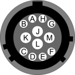
16.5.6 Cylinder: GPIO
These are standard 12-pin “mil-spec” sockets, conforming to MIL-DTL-26482 (formerly MIL-C-26482). A typical part-number is 02E-14-12S although the initial “02E” varies with manufacturer. Suitable mating connectors have part-numbers like ***-14-12P and are available from Amphenol, ITT Cannon and other manufacturers. |
|
The USB lines provide external host access to the internal USB memory device. When power is sensed on pin J, an internal switch disconnects the memory device from the internal circuitry and connects it to this socket.
Pin | Function |
A | USB Data -ve (USB Type A pin 2) - see text above. |
B | USB Data +ve (USB Type A pin 3) - see text above. |
C | Anti-tamper line 4 |
D | Anti-tamper line 3 |
E | Anti-tamper line 2 |
F | Anti-tamper line 1 |
G | Console transmit (RS232 TXD) |
H | Console receive (RS232 RXD) |
J | USB Power input (USB Type A pin 1) - see text above. |
K | USB Ground (USB Type A pin 4) |
L | Anti-tamper line 0 |
M | Ground |
| Wiring details for the compatible plug, ***-14-12P, as seen from the cable end (i.e. during assembly). |
16.5.7 Cylinder: GPS
This is a standard 10-pin “mil-spec” plug, conforming to MIL-DTL-26482 (formerly MIL-C-26482). A typical part-number is 02E-12-10P although the initial “02E” varies with manufacturer. Suitable mating connectors have part-numbers like ***-12-10S and are available from Amphenol, ITT Cannon and other manufacturers. |
|
The pin-out is the same as the GPS input of a DM24 digitizer.
Pin | Function |
A | Power 0 V |
B | Power +12VDC |
C | 1pps signal |
D | not connected |
E | Digitizer console transmit |
F | Digitizer console receive |
G | RS232 ground |
H | Digitizer console ground |
J | RS232 transmit to GPS |
K | RS232 receive from GPS |
| Wiring details for the compatible socket, ***-12-10S, as seen from the cable end (i.e. during assembly). |
16.5.8 Cylinder: USB
This is a standard 6-pin “mil-spec” socket, conforming to MIL-DTL-26482 (formerly MIL-C-26482). A typical part-number is 02E-10-06S although the initial “02E” varies with manufacturer. Suitable mating connectors have part-numbers like ***-10-06P and are available from Amphenol, ITT Cannon and other manufacturers. |
|
Pin | Function |
A | +5 V DC (USB Type A pin 1) |
B | Data –ve (USB Type A pin 2) |
C | Data +ve (USB Type A pin 3) |
D | 0 V (USB Type A pin 4) |
E | Shielding |
F | not connected |
| Wiring details for the compatible plug, ***-10-06P, as seen from the cable end (i.e. during assembly). |
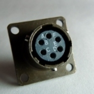
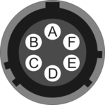
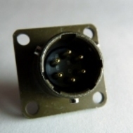
16.5.9 Cylinder: Power
This is a standard 4-pin “mil-spec” plug, conforming to MIL-DTL-26482 (formerly MIL-C-26482). A typical part-number is 02E-08-04P although the initial “02E” varies with manufacturer. Suitable mating connectors have part-numbers like ***-08-04S and are available from Amphenol, ITT Cannon and other manufacturers. |
|
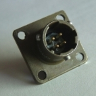
Pin | Function |
A | Ground |
B | Power input +10 to +36VDC |
C | Anti-tamper line 5 |
D | External switched power output #1 |
| Wiring details for the compatible socket, ***-08-04S, as seen from the cable end (i.e. during assembly). |
16.5.10 Cylinder: Ethernet
This is a standard 6-pin “mil-spec” plug, conforming to MIL-DTL-26482 (formerly MIL-C-26482). A typical part-number is 02E-10-06P although the initial “02E” varies with manufacturer. Suitable mating connectors have part-numbers like ***-10-06S and are available from Amphenol, ITT Cannon and other manufacturers. |
|
Pin | Function |
A | Ground |
B | Data transmit +ve (RJ45 pin 1) |
C | Data receive +ve (RJ45 pin 3) |
D | External switched power output #0 |
E | Data receive –ve (RJ45 pin 6) |
F | Data transmit –ve (RJ45 pin 2) |
| Wiring details for the compatible socket, ***-10-06S, as seen from the cable end (i.e. during assembly). |
16.5.11 Cylinder: Data
This is a standard 10-pin “mil-spec” plug, conforming to MIL-DTL-26482 (formerly MIL-C-26482). A typical part-number is 02E-12-10P although the initial “02E” varies with manufacturer. Suitable mating connectors have part-numbers like ***-12-10S and are available from Amphenol, ITT Cannon and other manufacturers. |
|
Pin | Function |
A | Power input, 0 V |
B | Power input +10 to +36VDC |
C | RS232 CTS |
D | RS232 RTS |
E | External trigger output |
F | External trigger output |
G | RS232 ground |
H | External trigger input |
J | RS232 receive |
K | RS232 transmit |
| Wiring details for the compatible socket, ***-12-10S, as seen from the cable end (i.e. during assembly). |
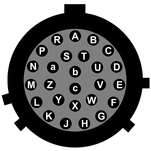
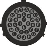
16.5.12 Sensor Port
This is a standard 26-pin “mil-spec” plug, conforming to MIL-DTL-26482 (formerly MIL-C-26482). A typical part-number is 02E-16-26P although the initial “02E” varies with manufacturer. Suitable mating connectors have part-numbers like ***-16-26S and are available from Amphenol, ITT Cannon and other manufacturers. |
|
Pin | Function | Pin | Function |
A | Vertical velocity +ve | P | Calibration signal |
B | Vertical velocity –ve | R | Vertical calibration enable |
C | N/S velocity +ve | S | N/S calibration enable |
D | N/S velocity –ve | T | E/W calibration enable |
E | E/W velocity +ve | U | Centre |
F | E/W velocity –ve | V | Active-high – see section 14.3.2 |
G | Vertical mass position | W | Unlock |
H | not connected | X | Lock |
J | N/S mass position | Y | Logic signal ground |
K | Busy indicator LED | Z | not connected |
L | E/W mass position | a | not connected |
M | not connected | b | Power 0 V |
N | Signal ground | c | Power output +10 to +24VDC |
| Wiring details for the compatible socket, ***-16-26S, as seen from the cable end (i.e. during assembly). |
16.5.13 Cylinder: Auxiliary Input
This is a standard 19-pin “mil-spec” plug, conforming to MIL-DTL-26482 (formerly MIL-C-26482). A typical part-number is 02E-14-19P although the initial “02E” varies with manufacturer. Suitable mating connectors have part-numbers like ***-14-19S and are available from Amphenol, ITT Cannon and other manufacturers. |
|
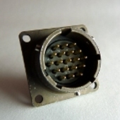
Pin | Function | Pin | Function |
A | Optional SENSOR B auxiliary / calibration channel +ve | L | SENSOR A signal ground |
B | Optional SENSOR B auxiliary / calibration channel –ve | M | Optional SENSOR B |
C | Optional SENSOR B signal ground | N | Digital ground |
D | Optional SENSOR B Mux channel M3 | P | not connected |
E | Optional SENSOR B Mux channel M4 | R | SENSOR A Mux channel MB |
F | Optional SENSOR B Mux channel M7 | S | SENSOR A Mux channel MC |
G | not connected | T | SENSOR A Mux channel MF |
H | Optional SENSOR B Mux channel M5 | U | SENSOR A Mux channel MD |
J | SENSOR A auxiliary / calibration channel +ve | V | SENSOR A Mux channel ME |
K | SENSOR A auxiliary / calibration channel –ve |
| Wiring details for the compatible socket, ***-14-19S, as seen from the cable end (i.e. during assembly). |
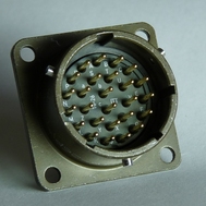
16.5.14 DM24S24EAM: Sensor Inputs
This is a standard 32-pin “mil-spec” plug, conforming to MIL-DTL-26482 (formerly MIL-C-26482). A typical part-number is 02E-16-32P although the initial “02E” varies with manufacturer. Suitable mating connectors have part-numbers like ***-16-32S and are available from Amphenol, ITT Cannon and other manufacturers. |
|
Pin | Function | Pin | Function |
A | Channel 0 +ve | T | E/W calibration enable |
B | Channel 0 –ve | U | Centre |
C | Channel 1 +ve | V | not connected |
D | Channel 1 –ve | W | Unlock |
E | Channel 2 +ve | X | Lock |
F | Channel 2 –ve | Y | Logic signal ground |
G | Vertical mass position | Z | not connected |
H | not connected | a | not connected |
J | N/S mass position | b | Power 0 V |
K | Busy indicator LED | c | Power output +10 to +24VDC |
L | E/W mass position | d | Channel 3 +ve |
M | not connected | e | Channel 3 –ve |
N | Signal ground | f | Channel 4 +ve |
P | Calibration signal | g | Channel 4 –ve |
R | Vertical calibration enable | h | Channel 5 +ve |
S | N/S calibration enable | j | Channel 5 –ve |
| Wiring details for the compatible socket, ***-16-32S, as seen from the cable end (i.e. during assembly). |
16.6 Appendix F – Open source software and the GPL
16.6.1 Introduction
Platinum firmware contains open-source programs covered by the GNU Public License (GPL). The exact details vary from release to release but full, current details are always available from our web site at http://www.guralp.com/platinum/opensource/.
16.6.2 Physical copies of source code
Under the terms of the GPL, GSL has an obligation to offer to ship the source code for such programs (and associated build scripts) on a physical storage medium customarily used for information interchange, such as a CD. If you would like the source code in physical format, please contact support@guralp.com. A small charge will be made for administration, the medium and postage.
16.6.3 The GNU General Public License
The license itself is available on the web at www.gnu.org/licenses.