Chapter 4. System Description
Depending on your chosen deployment type and depth, the Güralp Radian seismometer can be delivered in two forms: the Radian Post-hole or the Radian Bore-hole. A Surface Interface Unit (SIU), accessories (cables and connectors etc.), and software will also be supplied to provide a fully operational system.
This Section describes the two main variants of Radian instrument and the primary components that constitute a full Radian system.
Note: Owing to the Radian’s proprietary digital output, it can only be used in combination with a Surface Interface Unit (SIU), such as the Güralp Minimus.
4.1 Güralp Radian Post-hole Digital Seismometer
The Radian Post-hole instrument comprises a triaxial broadband seismometer and 24-bit digitiser (i.e. digital seismometer) inside a robust 55 mm diameter stainless steel casing. The main components of the Radian Post-hole are shown in the photo below; further description is given in the following text.
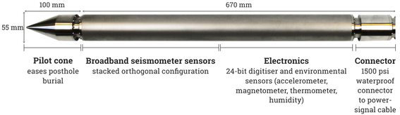
4.1.1 Pilot cone
The conical module at the bottom end of the Radian eases direct burial of the instrument into a post-hole.
4.1.2 Sensors
The broadband seismometer sensors are stacked vertically, allowing the instrument to have its very slim form factor. The sensors can be delivered with a frequency response (transfer function) that is flat to either velocity or acceleration. This option is decided by the customer upon ordering and normally depends on the anticipated seismic monitoring application. The sensors have a standard broadband frequency response of 120 s (0.0083 Hz) to 200 Hz. The unique sensor technology allows the sensors’ masses to fully centre regardless of orientation, allowing the Radian to be installed at any angle in the shallow sub-surface, facilitating rapid deployment.
4.1.3 Digitiser and electronics
The electronics module inside the Radian contains a 24-bit analogue-to-digital converter (ADC) that supports recording rates up to 5000 samples per second. The electronics system also stores instrument calibration parameters that can be transmitted across a network and/or recorded at the SIU.
4.1.4 Connector
The connector module comprises a 10-way female plug that is used to connect to the power/signal cable (see Section 4.3). The module is threaded on the outside to mate with the plug on the power/signal cable. The connector is rated waterproof to 10 MPa, 100 Bar or 1500 psi.
4.2 Güralp Radian Bore-hole Digital Seismometer
The Radian Bore-hole is designed for installations in cased bore-holes up to 2000 m depth. Apart from not having a pilot cone, the instrument consists of the same modules as the Radian Post-hole (Section 4.1), with two three-jaw hole-lock systems.
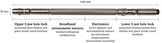
Main features of the Radian bore-hole digital seismometer
4.2.1 Three-jaw hole-lock system
The Radian’s hole-lock system is designed to maintain a positive pressure on the bore-hole casing over a prolonged period of time and to fix the instrument in place whilst avoiding the transmission of any stresses.
Hole-locks are located at the top and bottom of the Radian bore-hole instrument. Each three-jaw hole-lock provides excellent grip on the bore-hole casing; it can be installed in bore-holes with diameters of between 60 mm and 100 mm.
Each hole-lock consists of a set of three active clamp arms attached to a compression spring, which forces them to swing out from the instrument and wedge themselves against the bore-hole wall. Serrated steel jaws at the end of each arm provide maximum grip against the bore-hole casing. This configuration ensures that the sonde body is held parallel to the axis of the bore-hole and prevented from twisting or slipping under the influence of ground vibrations.
The hole-locks can be easily controlled using the Discovery software (see Section 4.6) using a PC or laptop (see Section 5.5).
4.3 Power/signal cable
The supplied power/signal cable connects the SIU with the Radian Post-hole instrument.
At the instrument end of the cable, there is a waterproof (10 MPa or 1500 psi) 10-way military-specification connector. This connector must be connected and attached firmly by hand-tightening the screw cover. At the SIU end, there is a standard 10-way military-specification bayonet connector which should be attached to the port labelled “DIGITAL”.
4.4 Surface Interface Unit for post-hole and shallow bore-hole installations
Please refer to Sections 3.1 and 3.2 of MAN-MIN-0001 for full details of the Surface Interface Unit (SIU) / Minimus and its Accessory Pack.
4.4.1 Connectors
The Surface Interface Unit has a total of five connectors that are clearly labelled as follows:
Caution: Use attached dust-caps where possible to prevent ingress of any dirt, dust or fluids. Any such foreign bodies may compromise the operation of the connectors.
Sensor (“ANALOGUE”) connector
The 26-pin military-specification “ANALOGUE” connector allows the SIU to be connected to a standard analogue seismic seismometer or accelerometer with three primary channels and one auxiliary channel; e.g. Güralp Fortis, 5TC, 3T, 3ESPC, 40T, 6T or a third-party sensor.
Network (“ETHERNET”) connector
The 8P8C Ethernet connector allows use of 10BASE-T, 100BASE-TX or 1000BASE-T networks.
Power supply (“POWER”) connector
The SIU accepts power from lines in its “POWER” connector. This is a Güralp standard 4-pin bayonet plug conforming to MIL-DTL-26482.
Radian (“DIGITAL”) connector
This connector mates with the down-hole cable to the first or only Radian in a bore-hole string.
GNSS / GPS and Serial (“GPS”) connector
This is a LEMO connector that connects either to the GNSS cable and receiver or to a LEMO-to-Serial adapter for debugging purposes.
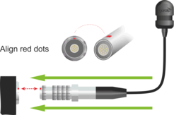
LEMO connectors use an innovative latching mechanism which is different to the bayonet connectors used elsewhere. To mate, simply line up the red marks and gently push the connector into place. To disconnect (un-mate), grasp the outer sleeve of the connector and pull gently.
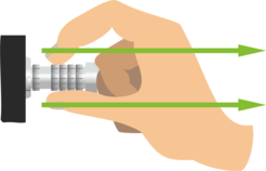
Caution: Do not twist the connector.
Top-down view of the SIU shallow variant
Side connector-panel of the SIU shallow variant2
4.5 Surface Interface Unit for deep multi-instrument bore-hole installations
For multiple-instrument bore-hole installations (i.e. vertical array / VSP tool applications) and/or at installation depths greater than 100 m, the deep variant of the SIU must be used.
The deep SIU is similar to the shallow version and contains almost identical internal electronics. The main difference between the variants is the size of the enclosure; this difference is because of the larger voltage output required for deep, multi-instrument bore-hole installations and the incorporation of fibre optic media converters.
4.5.1 Connectors
Caution: Use dust-caps where possible to prevent ingress of any dirt, dust or fluids. Any such foreign bodies may compromise the operation of the connectors.
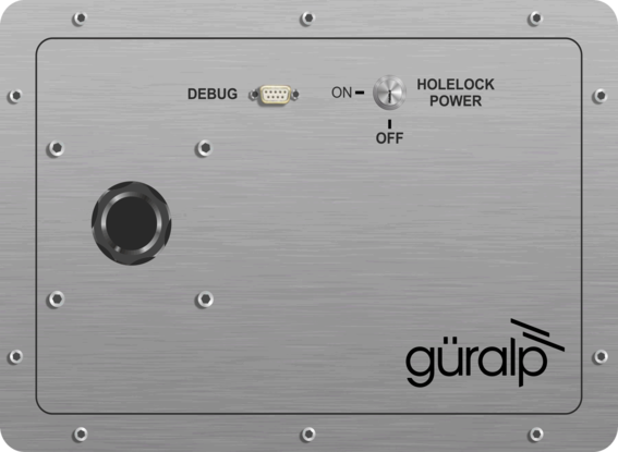
Serial (“DEBUG”) connector
This is a standard DE9m serial port which can be connected to a terminal emulator using either a standard serial cable or an RS232-to-USB converter.
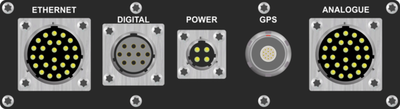
Network (“ETHERNET”) connector
The 8P8C Ethernet connector allows use of 10BASE-T, 100BASE-TX or 1000BASE-T networks.
Power/signal connector (“DIGITAL”)
This connector mates with the down-hole cable to the first or only Radian in a bore-hole string.
Warning: The “DIGITAL” connector can present voltages in excess of 200 Volts. Take extreme care not to touch this connector and to ensure that water does not enter this connector when the Surface Interface Unit receives power.
GNSS / GPS (“GPS”) connector
This is a ten-pin, military-specification bayonet connector that connects to the GNSS cable and receiver.
LEMO connectors use an innovative latching mechanism which is different to the bayonet connectors used elsewhere. To mate, simply line up the red marks and gently push the connector into place. To disconnect (un-mate), grasp the outer sleeve of the connector and pull gently.
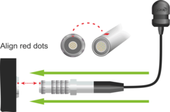

Caution: Do not twist the connector or use any tools.

“ANALOGUE” connector
This allows the connection of an analogue instrument, the output of which will be digitised by the ADC of the internal Minimus. For specifications, please see MAN-MIN-0001.
4.6 Güralp Discovery software and GüVü app
Please refer to Sections 3.3 and 3.4 of MAN-MIN-0001 for full details on Güralp Discovery and Güralp GüVü.