Chapter 5. The 6TC control menu
Note: Refer to Appendix A on page 13 for information on connector pin-outs.
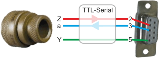
The CMG-6TC has a serial console, which can be accessed via pins Y (ground), Z (console output) and a ( console input) of the connector. This is a TTL-level interface (rather than RS232) so a suitable adaptor is required before it can be interfaced directly to, say, a PC or laptop.
Using a suitable TTL-to-USB or TTL-to-Serial adaptor, connect pins Y, Z and a on the instrument connector to a PC.
Connect the instrument to a power supply as follows:
If using the optional Güralp supplied cable, a DC supply of between 9V and 36V is required.
If you are connecting directly to the instrument, a ±5V DC supply is required.
Open a connection from the PC to the instrument using terminal emulator software such as: minicom or picocom (Linux); or Hyperterminal or PuTTY (Windows). Configure the connection to 38,400 baud, 8 data bits, no parity bits, 1 stop bit (“8-N-1”) and no hardware or software flow-control.
Once a connection has been established, disconnect and re-connect the instrument's power supply to re-boot it.
The boot sequence should look something like this:
Guralp Systems Ltd 6TC SoH v1.0 mgs 29/06/11 (Build 07f)
Built 29 Jun 2011, 15:44:16
Red Amber
W6461 T6E90 Green
System Test Passed
ESC for manual control 5 4 3 2 1 0To access the control menu press the
 key before the figures indicated in red count down to zero.
The control menu looks like this:
SENSORS : A_ll, V_ertical, N_orth, E_ast – centre
MODE : S_hortperiod, B_roadband, R_esponse
M_ass positions : I_inclination : O_ffset null ADXL : e_X_it :- KEY ?To exit the control menu and continue with a normal system start, press the
 key. For explanation of all other keys, please see the following sections.
After any control menu operation is completed, the control menu will re-display.
5.1 Sensor centring
To centre the sensors, press the  ,
,  ,
,  or
or  keys as required.
Keying will centre all components while , or will centre the vertical, North/South or East/West masses, respectively.
The sensors will auto-centre during start up: manual centring is only required for diagnostic or testing purposes.
5.2 Response mode
Option  displays the following menu, used for selecting the response mode:
Select System Bandwidth 0=LP, 1=LMP, 2=SMP, 3=SP
The response mode options are given in the following table:
Required Response | Menu Key | Designation | |
Build Version A | Build version B | ||
1 | 1 |
| SP |
10 | 30 |
| SMP |
30 | 60 |
| LMP |
60 | 120 |
| LP |


In addition to configuring the mode for normal operations, it is also possible to set the instrument temporarily into short-period mode, in order to assess the effects of adjustments to the instrument's inclination during installation.
Option  (Short-period mode) over-rides any selected response mode (whether hardware or software configured) and temporarily changes the response mode to one second (SP) for as long as the control menu is active – i.e. until the system is allowed to boot normally or “broadband mode” is selected (see option
  , below).
Option (Broadband mode) cancels the temporary short-period mode and restores the configured response mode. Note that, when the instrument boots, it will always revert to the normally configured response mode.
5.3 Other controls
Option  displays the current mass positions.
Option  returns the internally measured inclination.
Option  resets the offset-null. This can be used when the internally-measured inclination appears to be different to the actual inclination. Resetting the offset should result in an internally measured inclination reading of 0°, regardless of the actual, physical inclination.
Option exits the control menu and continues with the normal boot process.