Chapter 3. The procedure
3.1 Prerequisites
Assemble the following equipment before commencing any work
A clean environment in which to work, including suitable ESD equipment (dissipative surface, wristband, etc).
A 2mm hexagonal driver
A medium-sized, flat-bladed screw-driver
A roll of aluminium foil
A sharp knife or scalpel
A tube of one-component room-temperature vulcanizing silicone (RTV-1) or equivalent silicone adhesive/sealing compound. Dow-Corning 744 is suitable and widely available from hardware stores.
The replacement USB memory device
Clean the outside of the instrument thoroughly using compressed air and/or alcohol before taking it into the clean work area, to prevent any dust from the casing entering the instrument.
3.2 Replacing the memory
The instrument lid is secured using a number of small screws located around the top, outside edge. The lid extends a short way down inside the cylindrical casing and two 'O'-rings provide sealing between the lid and the cylinder. The seal thus formed can make it difficult to remove the lid due to the differential pressure between the inside and the outside of the casing. A pressure-relief screw is provided for this reason - but see the Warning in the description below.
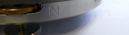
Locate the North indicator on the base of the instrument. This may be a stamped 'N' or a gold-coloured stud. If no such indication can be found, use a permanent marker to mark the position of the lid with respect to the cylinder:
Using the 2mm hexagonal driver, remove the screws around the top edge of the cylinder:
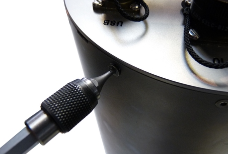
Using the flat-bladed screwdriver, remove the pressure relief screw from the top of the lid:
Warning: Instruments are assembled near sea level. If working at altitude, there may be a considerable pressure difference between the inside of the instrument and local atmospheric pressure. Ensure that the pressure-relief screw does not fly off when released. Failure to do so may cause injury.
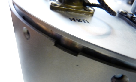
Remove the lid from the instrument. It will, initially, be difficult to remove because of the 'O'-rings. The electrical connections between the lid electronics and the rest of the instrument are via a 150mm ribbon cable so it is acceptable to rotate the lid slightly to ease it from its seal. Be careful not to rotate it too far - 10° or so in either direction is a safe limit. If the lid proves very hard to move, a flat-headed screw-driver can be inserted into the small slot formed by a cut-out in the top of the cylinder and used for leverage:
Caution: The force required will drop significantly when the 'O'-ring seals become clear of the the top of the cylinder. Take particular care that the lid does not “fly off” when this happens.
Lift the lid away from the cylinder and, wearing an anti-static wrist-band, disconnect (at either end) the ribbon cable connecting it to the lower electronics:
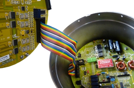
Immediately cover the body of the instrument with aluminium foil to prevent any ingress of dust or dirt.
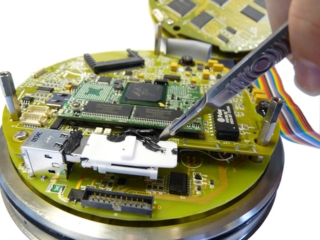
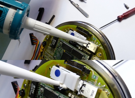
Before proceeding, locate the USB socket, which is near the edge of the assembly, as shown in the photograph below. Check carefully that there is a clear gap between any existing RTV (which may be black or, as shown, white) and the coil mounted on the third card from the lid (ringed in the photograph).
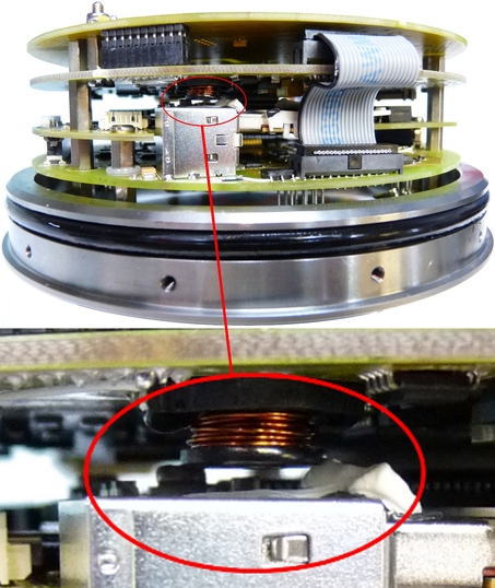
There will normally be no contact between the two but we have seen examples (where a liberal application of RTV has been made and the stack assembled before the RTV has dried) where the coil has become embedded in the RTV. This has no functional implications for the instrument but raises the possibility of damaging the coil during the disassembly. If the coil is in contact with or embedded in the RTV, carefully use a scalpel or sharp knife to remove enough RTV to allow the card stack to be split in two without risk of damage to the coil.
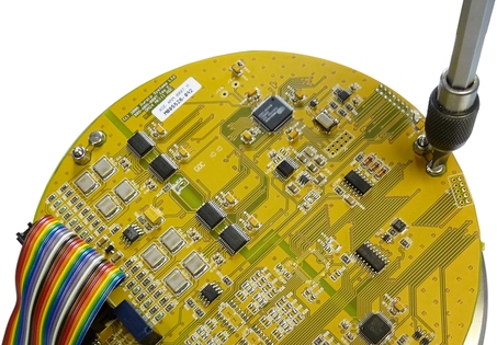
Support the lid assembly with the handle downwards and locate the three slot-headed screws securing the top-most two PCBs. They are located at 120° to each other around the outer edge. Using a flat-bladed screwdriver, remove all three:
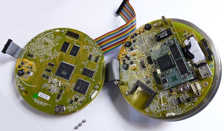
Some variants use two ribbon cables to connect the top two PCBs to the rest of the stack; others use just one. If two ribbon cables are present, disconnect the narrower of the two.
Swing the top two circuit cards away from the others, allowing the ribbon cable to function as a hinge:
Locate the USB memory device, which is held in place using RTV. Using a scalpel or sharp knife, with the blade pointing away from the PCB, carefully remove the RTV from the side and connector of the memory device:

Withdraw the memory device and carefully remove any larger loose lumps of RTV from the socket and adjacent daughter-board. It is not necessary to completely clean either; simply remove any loose pieces in order to provide a firm anchor point for the RTV that secures the replacement device.
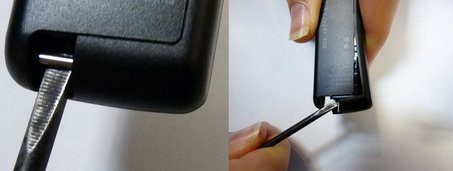
If the replacement USB memory device is cased, it is necessary to remove the casing to free the memory carrier.
Note: Güralp no longer supply memory devices of the type shown in these illustrations. The currently-supplied model does not need de-casing.
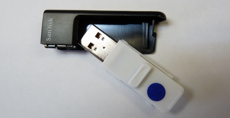
For those formerly supplied by Güralp, a small screwdriver can be inserted into a recess in the base of the device and levered sideways to crack the casing open:
The memory carrier can then be withdrawn:
Place the memory carrier in the socket:
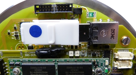
Secure the carrier in place using a bead of RTV along the edge of the adjacent daughter-board and another along the edge of the connector:
Close the two halves of the lid assembly (replacing the short ribbon cable if it was removed). Secure with the three screws.
Remove the temporary covering from the instrument and plug in the ribbon cable connecting it to the lid assembly.
Check the ‘O’-ring seal for any sign of damage or contamination. Contact Güralp support if it is damaged; Clean it if it is contaminated, then re-lubricate with a thin smear of waterproof grease, if necessary.
Replace the lid, carefully aligning the “North” marker on the handle to that on the instrument base (or to your own marks, if you made any).
Gently push the lid completely home and make sure that the screw-holes on the cylinder side align with those in the lid.
Replace the screws in the cylinder side, securing the lid to the cylinder.
Caution: Do not over-tighten the screws: this can distort the casing and compromise the seal. They need only be tight enough to be secure.
Inspect the pressure relief screw. Clean it if it is contaminated, then re-lubricate with a thin smear of waterproof grease, if necessary. Replace the pressure relief screw in the lid.
The instrument is now ready for testing.