6TD installation
Guralp Systems 6TD seismometers are ideal for cost-effective, rapid seismic installations:
-
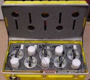
A set of five instruments weighs less than 30 kg, and occupies a space of under 120 × 60 × 60 cm in an optional, specially-designed, waterproof transport-case.
-
Power and data distribution units are included in the transport case, allowing you to test them in place. You do not have to unpack any instruments until you are ready to install them.
-
The sensors do not require levelling, unlocking, or centring, as long as they are placed in a stable orientation within 3 ° of the vertical: they begin measuring signals as soon as you power them up.
-
After the sensors are recovered, you can download the data onto Güralp FireWire disks simply by plugging in the disk and turning on the sensor.
-
Alternatively, you can re-pack the sensors in the transport case and use the power and data distribution units to download stored data from the entire array over a single USB connection.
This page describes the entire procedure of testing and installing an array of 6TD instruments, from delivery to operation.
Unpacking and testing
Unpacking and packing
The 6TD seismometer is delivered in a single transportation case. The packaging is specifically designed for the 6TD and should be reused whenever you need to transport the sensor. Please note any damage to the packaging when you receive the equipment, and unpack on a safe, clean surface. For each instrument in the packaging, you should have received:
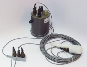
- the seismometer;
- the breakout box (which provides separate connections for the signal, control and power lines);
- a Guralp GPS receiver unit with mounting rod;
- a waterproof IEEE.1394 (FireWire) cable;
- a 15 m GPS cable, with 6-pin mil-spec connectors at both ends;
- a power supply cable, with bare wires at one end and a 10-pin military-specification bayonet socket at the other;
- a serial data cable, with a standard 9-pin D connector at one end and a 10-pin military-specification bayonet plug at the other;
- a calibration and installation sheet.
If you have ordered several instruments together, you can test them together using power and data distribution units inside the case.
Assuming all the parts are present, stand the seismometer in the centre of a bench and identify its external features:
- a handle with North indication,
- a multi-pole socket for input and output,
- a spirit level,
- three adjustable feet, and
- two accurate orientation pins (one brass and one steel).
Serial number
The sensor’s serial number is stamped onto the side of the sensor base, next to the N/S indicator. It can also be found on the label stuck to the top lid of the sensor, and stamped into the lid itself. You should quote this serial number if you need assistance from Guralp Systems.
Test installation
This section gives an overview of how to set up a 6TD and begin recording data. We recommend that you set up a test instrument in your office or laboratory as a “dry run” to gain a basic understanding of the system and to check that it is functioning as expected.
This test installation will use the instrument’s default settings. Data will be received using Guralp Systems’ Scream! software, available from our website.
You will need access to a PC with a 9-pin RS232 port, and a 12 V power source.
-
Connect the wire from the breakout box to the 6TD’s 10-pin data connector.
-
Connect the 6-pin connector on the breakout box to the GPS unit using the GPS cable. Position the GPS so that it has a good view of the sky.If you do not have a view of the sky, you can operate the sensor without a GPS unit, but timing information may be inaccurate.
-
Connect the 10-pin data socket on the breakout box to the 9-pin RS232 port on your PC using the serial cable.
-
Use the power cable to connect the 10-pin power plug on the breakout box to your power source.The instrument is now fully operational, and will already be recording data.
- Install Scream! on your PC and run it.
-
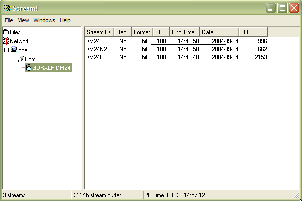
After a few seconds you should see the 6TD’s digitiser appear under Network → Local → Com1 in the left-hand panel of Scream!’s main window. (If your PC has multiple serial ports, it may appear under some other Comn port name.) Soon after, data streams will begin appearing in the right-hand panel. Streams with higher sample rates will appear sooner than those with lower sample rates.
If this does not happen, check all connections, and ensure the power supply is providing the correct voltage and current.
-
Each data stream has a Stream ID, a six-character string unique to it. Stream IDs normally identify the instrument, component and sample rate of each stream. Thus the stream 1026Z2 refers to a Z-component stream from instrument 1026, at tap 2. Data streams ending in 00 are status streams containing any extra information sent from the digitiser.
-
To view data, select a stream and then double-click to open a Waveview window.
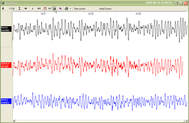
You can select several streams at once by holding down shift as you select, and then double-clicking the selection. You can also add data streams to an open Waveview window by dragging a selection onto it from Scream!’s main window.
-
To view status information, select the stream and right-click to open a pop-up menu. Select .
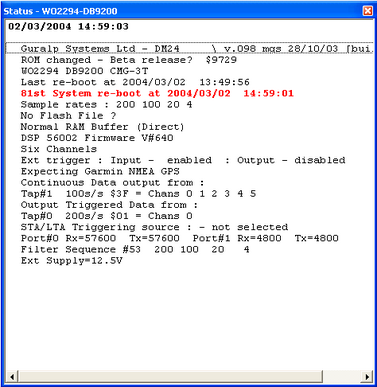
The first few status blocks will consist of the 6TD’s start-up messages, including its software revision number and the data streams selected for downloading and triggering.
Later blocks give information on the GPS system (number of satellites visible, the location of the GPS antenna, time synchronization status, etc) and the baud rates in use for each channel.
Testing several instruments together
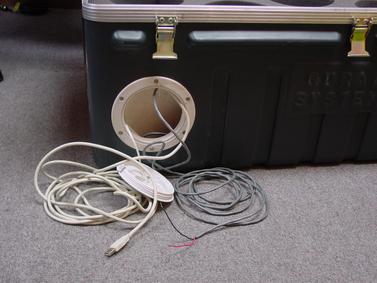
Each set of five 6TD instruments is delivered in a single rigid polyurethane transport case. Within this case, the sensors are packed so that you can huddle-test the sensors and view data in Scream! without needing to unpack them. This is done using a power distribution box and USB and FireWire data hubs built into the case.
-
The power and data distribution boxes are located at the front of the case.
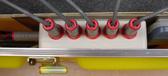
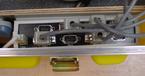
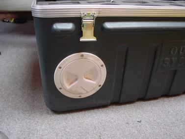
Each of the five power sockets should already be connected to one of the instruments inside. Likewise, there should be five RS232 plugs connected to the data unit, one for each instrument. These units are connected to power and data cables, which can be accessed through the waterproof port to the left of the front panel of the case.
-
Unscrew the port cover, and pull out the ends of the power and USB cables.
-
Connect the power cable to your power source, attaching a suitable connector, if necessary.
- Connect the USB data cable to your PC.
-
Install Scream! on your PC and run it.
-
After a few seconds you should see the five instruments appear under Network → Local → Com1 in the left-hand panel of Scream!’s main window. (If your PC has multiple serial and USB ports, it may appear under some other Comn port name.) Soon after, data streams will begin appearing in the right-hand panel. Streams with higher sample rates will appear sooner than those with lower sample rates. If this does not happen, check that the the power supply is providing the correct voltage and current.
-
To view data, select a stream and then double-click to open a Waveview window.
-
Also within the case is a IEEE.1349 (FireWire) hub for you to test high speed data transfer. You will need to connect FireWire cables between the hub and the instruments to do this. Once the instruments are connected, you can access them all through the FireWire data cable, which is also accessible through the waterproof flap.To upload stored data from the array when it is stored in its transport case, simply attach a hard disk to the case and power up the array using the case’s built-in power distribution unit.Alternatively, you can attach a PC to the USB case’s connector and download all stored data using Scream!.
You can view several streams at once by holding down shift as you select, and then double-clicking the selection.
You can also add data streams to an open Waveview window by dragging a selection onto it from Scream!’s main window.
Installation
The 6TD is specially designed for rapid installation, and may be fully installed in a few hours. This section details a method of deploying 6TD instruments with the minimum of additional equipment. This is recommended for situations where seismic instrumentation needs to be installed very quickly, e.g. to study a resumption of volcanic activity, or where difficulty of access to the site prevents you from constructing a full seismic pit.
-
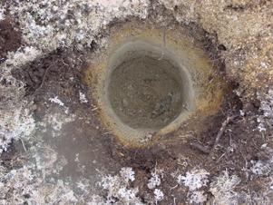
Prepare a hole of 60 – 90 cm depth to compacted subsoil, or down to the bedrock if possible.
-
Clean the hole down to the bottom, and remove any loose material from the mouth. Ensure that the bottom of the hole is relatively flat.
-
If the bottom of the hole is made of hard rock, you may need to put in some loose sand or soil so that the sensor can be levelled.
-
Connect the sensor to cables for the GPS unit and power source.
-
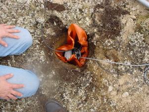
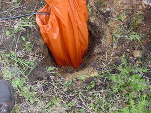
Carefully insert the instrument into the hole, protected by a tough plastic bag to keep water out. Use a bag strong enough to bear the weight of the sensor and breakout box, so that it can be recovered easily.
-
Press the sensor down firmly into the soil, without tapping or hitting it.
-
Check the bubble level on top of the instrument package:
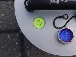
Adjust the instrument’s position if necessary so that the bubble lies entirely within the black circle.
-
Pack soil or sand around the instrument to hold it steady. Make sure the soil or sand is firmly compacted and not at all loose.
-
Recheck the bubble level. If you cannot adjust the soil packing at this stage and the sensor is not level, you will need to clear the hole and restart from step 3.
-
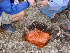
Once the sensor is level and soil is adequately packed around it, place the breakout box and any excess cable on top of the sensor, inside the plastic bag.
-
Group the cables coming from the bag for a distance of about 1 m, and keep them together with insulating tape.
-
Tie the top of the package and fold it over so that water cannot get in. Leave any excess cable within the bag.
-
Cover the installation with soil or sand until it is no longer visible.
-
Attach a GPS unit to the cable coming from the sensor. Seal the connection between the data cable and the GPS unit’s IEEE 1394 cable inside a plastic bag to protect it from moisture.
-
Position the GPS unit so that it has a good view of the sky. Bury the cable and connector package so that they cannot be seen.
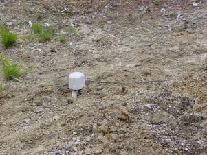
If possible, place the GPS near the instrument so that it can be found more easily, and the connector package near the GPS so you can retrieve data from the instrument without affecting the installation.
-
If you are using a battery as a power source, dig a second hole for it. This hole does not need to be as deep as the pit for the instrument: the height of the battery plus a further 100 mm should be enough.
-
Attach the sensor power cable to the battery, and wrap it in another plastic bag. Place the bag in the hole.
Tie the bag and fold over, to make the battery as waterproof as possible.
-
Bury the power cable between the battery and the instrument, and compact soil or sand around the bag.
-
Fill in and cover the hole so that it is not visible.
Recovery
You should recover the 6TD with care, since tapping or banging it can cause damage to the sensors inside. The following instructions assume that you have installed the instrument following the steps above.
-
Find the GPS receiver, which will be the only feature visible from the surface, and follow the buried data cable from it to the instrument.
-
Carefully remove earth from the hole until you find the power cable coming from the instrument.
-
Follow the power cable to the battery pit, and carefully dig away the soil to reveal the battery about 10 cm from the surface.
-
Disconnect the power cable from the battery. (With the power off, the sensor is less likely to suffer electrical damage during recovery.)
-
Return to the location of the sensor, and dig down to it. You should be able to remove a spade’s head depth of soil without hitting the instrument. Beyond that, using a small hand shovel, follow the wires and carefully remove the remaining soil until you can see the plastic bag. Take special care not to damage the wires, which should be tied together in the vicinity of the bag.
-
Carry on removing soil, either with your hands or (very carefully!) with the shovel, until the whole bag is uncovered to about half the height of the instrument.
-
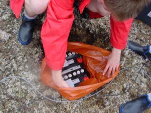
You should now be able to remove the sensor.If the hole is relatively dry, open the bag, remove the breakout box and cabling, and lift the instrument out by its handle. Do not lift the instrument by any of the attached cables. Straining the cables may result in invisible damage, making future installations unreliable.If the hole is waterlogged, carefully lift out the entire bag in one piece, and remove the contents at the surface.