Using GPS receivers with long cables
The accurate time-stamping of seismic data depends on the integrity of the signals received from the GPS receiver but this integrity can be compromised when long cables used. Güralp Systems’ DM24 GPS receivers will normally function well with cables up to 50 metres long but, in situations where it is impractical to place the receiver within 50 metres of the digitiser, several techniques are available to allow operation over distances up to 1 kilometre. This article discusses these techniques in relation to the GPS receivers used with DM24 digitisers.
Background information.
DM24 digitisers.
The DM24 digitiser is supplied as a stand-alone unit and is also integrated into data acquisition systems such as the DM24SxEAM and into digital instruments such as the 5TDE digital accelerometer. The GPS receivers supplied for use with DM24 digitisers can be identified by the presence of a 10-pin GPS connector. Güralp Systems also manufacture CD24 digitisers which have 6-pin GPS connectors: this article does not apply to systems with 6-pin GPS connectors.
Operating principles.
GPS receivers generate two outputs: an ASCII data-stream in NMEA 0813 format (usually known simply as “NMEA”) and a one-pulse-per-second signal (referred to as “PPS”). Both these outputs use TIA-232 (formerly known as RS-232) signalling standards. The NMEA conveys information about the number of GPS satellites visible and the location of the receiver, as well as the date and time, accurate to the nearest second. The PPS signal has a short, negative-going pulse accurately timed so that its leading edge is at the start of each second. The two signals combine to provide the accurate date and time information which is used to train the DM24′s internal clock.
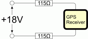
The GPS receiver requires between 12 and 36 Volts (DC) in order to operate correctly. This is normally provided by the DM24: the power input of the DM24 is connected via a switch to the power supply pins on the GPS connector.
Problems with long cable runs.
The use of long GPS cables can cause two separate problems: Firstly, ohmic losses in the cable can reduce the voltage seen by the receiver and, when these losses become too great, the receiver may not be supplied with enough voltage to operate; Secondly, the internal resistance, inductance and capacitance of the cable may degrade the NMEA and PPS signals to the point where they can no longer be accurately decoded by the DM24.
To illustrate the problem of ohmic losses, consider a 1,150 metre length of cable with a 0.1 Ω resistance per metre. The GPS receiver draws about 35 milliamperes of current so, by Ohm’s law, the voltage drop along the power supply core will be around 4 Volts (0.035 × 1150 × 0.1 ≈ 4). Note that the same current must also flow back along the ground core, so another 4 Volts will be dropped there. If the DM24 provides 18 Volts, the receiver will still only see 10 Volts because 8 Volts are “lost” in the cable.
The problem of signal degradation can perhaps best be illustrated by an oscillogram. The bottom trace in the image below represents a pulse train being sent down a long cable run. The top trace shows what is received at the other end of the cable: it is clear that the cable’s capacitance has increased the rise-time of each pulse and the inductance has caused over-shooting at the top and bottom of each pulse.
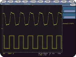
TIA-232 uses voltages for signalling. Ohmic losses caused by the cable’s resistance have decreased the amplitude of the pulses and the combination of longer rise-times and reduced amplitude will cause a measurable delay between the time each pulse is transmitted and the time that the received pulse crosses the TIA-232 threshold voltage. This will have an effect on the recovered pulse-train, reducing the accuracy of the time-stamping.
Solutions.
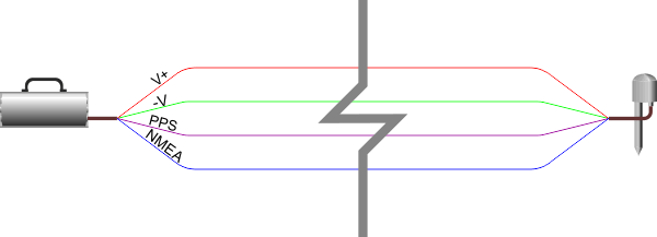
The standard connections for a GPS receiver are shown below:
Güralp Systems’ GPS cables attempt to reduce the effect of ohmic losses by using two cores for the power feed and the ground return, as shown here:
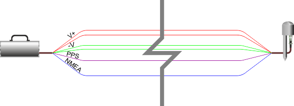
Where custom cables are being deployed, this technique can be used to reduce the voltage loss in the cable. In the example above involving 0.1 Ω/m cable, if two cores were used the voltage drop would be only 4 V (2 V each for the power and ground cores) and the receiver would see 14 V, allowing it to operate correctly. Selection of high-quality, low-resistance, low-capacitance cable also reduces signal degradation. Where cable runs of 100 m or more are required, however, additional measures may be required.
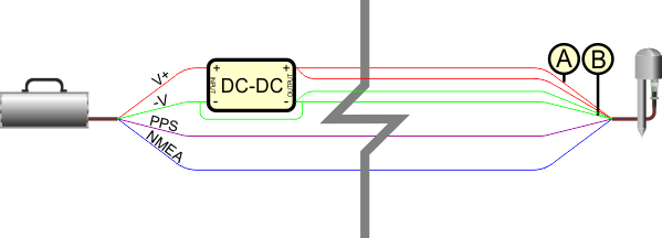
An alternative approach to working with ohmic losses is to increase the voltage supplied to the cable using a DC-DC converter inserted into the cable at the digitiser end. This allows the voltage to the receiver to be raised to an acceptable level without increasing the supply to the digitiser itself. The diagram below shows the arrangement:
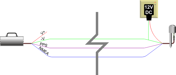
If power is available at the GPS receiver's location, a local 12 V D.C. isolating power supply can be used instead of an in-line DC-DC converter:
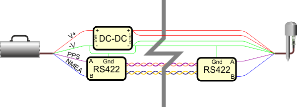
When extremely long cables are required, even the best quality cable will cause sufficient degradation of the signals to affect the resultant timing. In this case, it is necessary to use a signalling method other than TIA-232. TIA-232 uses voltages to represent '0's and '1's and this is inherently problematical. A signalling system that uses current, rather than voltage, is much more resilient when used with long cables. One such system is TIA-422 (formerly known as RS-422) and, since TIA-232—to—TIA-422 converters (often known as line-drivers) are easily available, this provides a simple and reliable way of conveying GPS signals along cables up to 1 km in length. A two-channel line-driver is required at each end: one channel carries the NMEA and the other carries the PPS. Two twisted pairs are normally required to carry the TIA-422 signals. The use of twisted pairs increases the immunity to electrical interference. The schematic below illustrates the use of both a DC-DC converter and a pair of line-drivers for use with very long cables.
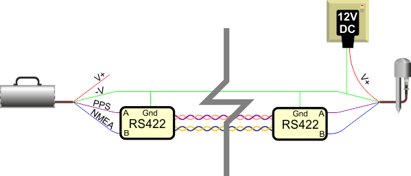
If power is available at the GPS receiver's location, a local 12 V D.C. isolating power supply can be used instead of an in-line DC-DC converter:
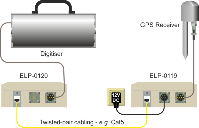
Güralp Systems provide the ELP-0119 and ELP-0120 units for this purpose. They provide a simple way to run GPS signals over low-cost twisted-pair cables using TIA-422:
Cable selection.
Güralp Systems’ GPS cables are constructed from custom-manufactured 7/02 (24 SWG) multi-cored cable and two cores each are used for the power and ground return lines. If you wish to make your own cables, you should select cable with an equivalent or heavier gauge, in order to minimise the series resistance, and with a low capacitance. If you intend to use TIA-422 line drivers, the cable should include at least two twisted pairs, to carry the NMEA and PPS signals. It will cause no problems if the power and ground lines are also carried on twisted pairs but this confers no advantage. Where the cable passes through areas containing electrical equipment, shielded cable can be used to reduce problems caused by of electrical interference.
Fibre Optics.
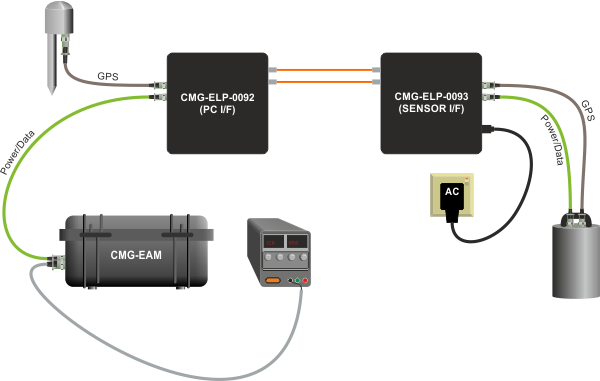
Güralp Systems can provide equipment to implement fibre-optic links for both GPS and serial data lines. The diagram below shows the use of CMG-ELP-0092 and CMG-ELP-0093 interfaces to extend GPS and serial data lines over multi-mode fibres with ST/BFOC (IEC 61754-2) connectors to a PC running Scream. This arrangement is suitable for distances of up to 600 metres.
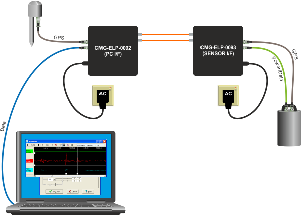
The CMG-ELP-0092 can also accept power via its serial port so, if used with an EAM, as shown below, a mains power supply is not required.
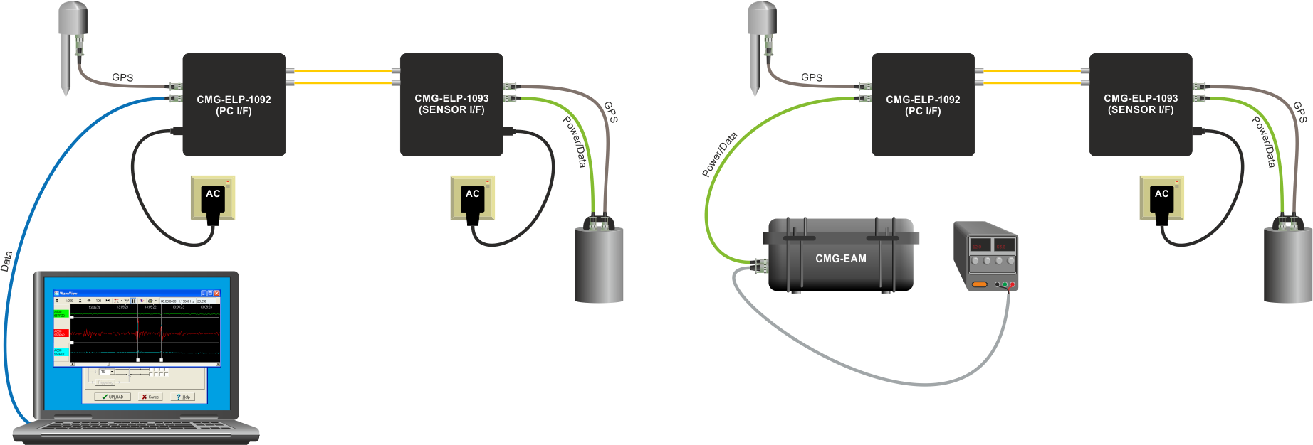
For longer cable runs, single mode fibres with SC (IEC 61754-4) connectors can be used in conjunction with CMG-ELP-1092 and CMG-ELP-1093 transceiver units. The hook-up arrangements are identical:
For more information about any of the topics discussed above, please contact .