Chapter 3. The procedure
3.1 Disassembling the instrument
Caution: Seismometers contain extremely sensitive mechanical components. Instruments with mass-locks must have the locks activated before they are opened or moved at all. Only open the casing of an instrument in a clean environment and take precautions to prevent any ingress of dust into the body of the instrument.
Caution: Circuit boards include components which can be damaged by electrostatic discharge. Always work on a properly grounded dissipative surface and wear a suitable grounded wristband. Ground yourself by touching an earthed conductor before handling any of the circuit boards.
Make alignment marks on the base, casing and lid so they can be assembled in the correct orientation.
Use a 2mm Allen key to remove the screws attaching the the lid onto the casing as shown:
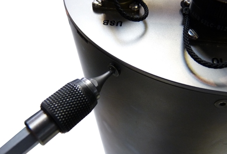
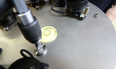
Using the flat-bladed screwdriver, remove the pressure relief screw from the top of the lid as shown
Warning: Instruments are assembled at sea level. If working at altitude, there may be a considerable pressure differential between the inside and the outside of the case. Take care that the pressure relief screw does not fly away.
Lever off the lid by placing a flat headed screwdriver in the notches provided and twisting.
Caution: The force required will drop significantly when the O-ring seals become clear of the the top of the cylinder. Take particular care that the lid does not “fly off” when this happens.
Lift the lid away from the casing, taking care not to stress the internal ribbon cable connecting the two.
Whilst wearing an anti-static wrist-band, disconnect the ribbon cable shown connecting the lid to the lower electronics.
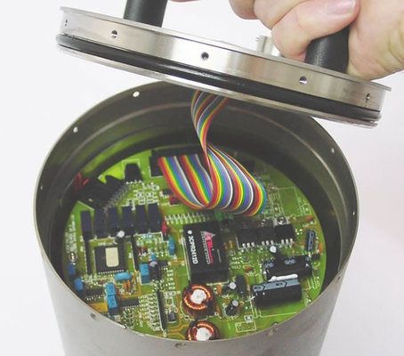
Note: Digital instruments have the digitiser PCB stack attached to the bottom of the lid. Analogue instruments have a bare lid, as shown above.
Place the lid assembly to one side in a static-safe environment (anti-static bag or dissipative work surface).
Use a 2mm Allen key to remove the screws attaching the the casing onto the instrument base plate.
Carefully lever off the casing from the baseplate using a flat headed screwdriver.
Lift off the casing slowly and vertically taking care not to knock or jar the mechanical components inside.
The top of the electronics stack of the analogue instrument should now be exposed. On many instruments, the SoH board is the topmost board of the stack. The SoH board can be identified by the presence of the large DC-DC converter in the centre of the board. Unplug any attached cables and use the M5 nut-spinner to remove the retaining nuts so that the SoH board can be lifted away. If the SoH board is not the top board, continue removing boards until the SoH board is free. Note carefully the order and orientation of each.
Caution: Verify that the SoH board is labelled ASE-ESP-0004 and do not proceed if it has a different label. In particular, ASE-T30-1027, ASE-T30-1028 and ASE-T30-4027 boards will be damaged if this procedure is performed on them.
3.2 Programming the parameter memory
The following procedure loads the contents of a parameter file into the parameter memory.
Note: This document does not cover choosing the correct parameter file. Please ensure that you have the correct file for the instrument into which the SoH board will be replaced.
Note: It is useful to have the parameter file for the target instrument easily at hand. A simple paper copy of each .txt file for visual reference has proved extremely useful in our experience. A simple pencil tick at each verified line helps to keep track of progress and is easily erased afterwards. Laminated copies and a “dry-wipe” pen would prove equally effective.
Plug the USB connector of the supplied programming cable into a spare USB port on your PC.
Windows will automatically assign a COM port number to the cable. Determine the COM port number by opening Device Manager. This typically involves
Click the start button
Right-click “My Computer”
Select “Manage” from the context menu
Double-click “Device Manager”
Expand the “Ports (COM and LPT) category by clicking on the '+' button
Look in the list for a USB Serial Port and read the COM number next to it.
If you have more than one USB Serial Ports, try unplugging and replugging the programming cable: the display will update in near-real time.
Connect a 12 V DC power-supply to the red and black terminals of the programming cable. Turn the power supply off.
Ensure that the in-line switch of the programming cable is set to the '0' position.
Connect the multi-way connector of the programming cable to the box header connector, J1, of the SoH board.
Turn on the power supply.
Open the terminal emulation software on the PC and configure it for 4800 Baud, 8 data bits, no parity bits, one stop bit (“8-N-1”) and no flow control – neither hardware (RTS/CTS) nor software (Xon/Xoff).
Press the Enter key to establish communication. The SoH processor should respond with a banner as follows:
CTRL = FF
Guralp SOH version 3.13 3EA
V Mass position = 0
N Mass position = 0
E Mass position = -1
U : unlock, L : Lock, C : centreMove the in-line switch of the programming cable to the '1' position. (This shorts both the LOCK and UNLOCK control lines to digital ground simultaneously, which activates the programming environment.)
Caution: Once the switch is in the '1' position, inadvertent key-strokes can cause significant problems.
Test the programming environment by requesting a read of memory location zero. To do this, enter the key sequence


 . The system should respond with something like
?R
00EE at 00 = 01
CTRL = FF
Guralp SOH version 3.13 3EA
V Mass position = 0
N Mass position = 0
E Mass position = -1
U : unlock, L : Lock, C : centreNote: Memory location zero stores the instrument type. See section 4.1 for full details of the memory address mapping.
3.2.1 Programming commands
As seen, memory can be read by typing  followed by the desired address, entered as two hexadecimal characters.
Note: It is not necessary to key “Enter” after entering the address and you should not do so.
To write memory, type  followed by
The address, entered as two hexadecimal characters
The data byte to be written, entered as two hexadecimal characters
The address repeated
The data repeated
For example, entering the sequence
W208C208C
will write the data 8C to memory location 20.
Note: All data and addresses are in hexadecimal.
This can be checked by entering the sequence
R20
to which the system will respond with something like
?R
20EE at 20 = 8C
CTRL = FF
Guralp SOH version 3.13 3EA
V Mass position = 0
N Mass position = 0
E Mass position = -1
U : unlock, L : Lock, C : centre
Using these two commands, the entire memory can be checked and re-written if necessary. When large numbers of changes are required, however, it is convenient to partially automate the process by entering multiple commands directly from a file. This is described in the next section.
3.2.2 Programming multiple memory locations
When multiple changes need to be made or the entire memory needs to be reprogrammed, the required parameters can be stored in a file which is pre-formatted as a list of write commands. This can then be injected directly into the terminal emulator session as if it had been keyed in. For this to work, the terminal emulator must support ASCII transfer-from-file or allow bulk pasting of commands. The technique described here uses HyperTerminal. Reconfiguration is required to restrict the rate at which characters are sent. If you choose to use another terminal emulator, you may have to experiment to achieve satisfactory results.
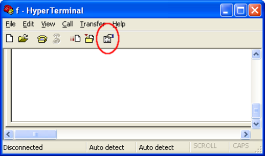
After having followed the preceding instructions to verify the programming environment, click the properties icon within HyperTerminal, as shown:
Go to the settings tab of the resulting dialogue and click  .
.
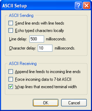
Configure ASCII Sending, setting the Line delay to 500 ms, the Character delay to 10 ms and the check-boxes as shown:
Click  to save these changes.
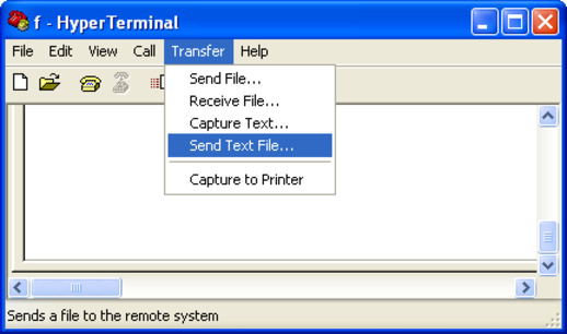
Select “Send Text File…” from the “Transfer” menu:
Browse to the location of your stored Parameter files and double click the appropriate .txt file.
File transfer will commence immediately and you will see each address being written to in turn. The entire process will take approximately 1 minute and the screen will stop scrolling upon completion.
3.3 Reassembly.
Reassembly is the reverse of the disassembly procedure but please note the following cautions:
Caution: Check that the two 'O'-ring seals are free of any dust or contamination and coated with a light, even coating of grease. Check that the mating surfaces are clear of any contamination.
Caution: Do not over-tighten the screws that hold the case to the lid and base. They need be only tight enough to be secure. They must not distort the cylindricality of the tube or they will compromise the seal.
Caution: Do not over-tighten the pressure-relief screw or you will damage the 'O'-ring seal. It need be only tight enough to be secure.