Chapter 3. First encounters
3.1 Handling notes
Although the 40T has a rugged design, it is still a sensitive instrument, and can be damaged if mishandled. If you are at all unsure about the handling or installation of the device, you should contact Güralp Systems for assistance.
Avoid bumping or jolting the sensor when handling or unpacking.
Do not kink or walk on the data cable (especially on rough surfaces such as gravel), nor allow it to bear the weight of the sensor.
Do not connect the instrument to power sources except where instructed.
Do not ground any of the signal lines from the sensor.
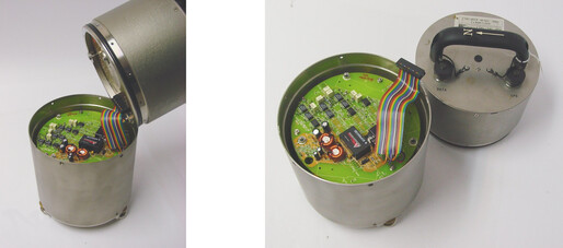
All parts of the 40T are waterproof.
3.2 Connections
The instrument has a single 26-pin military-specification bayonet connector which carries both power, control signals and output signals. This is suitable for connecting directly to a Güralp digitiser.
A breakout box is available which provides separate connectors for signal and power. An optional hand-held control unit provides individual connectors for every output signal. These are described in the following sections.
3.2.1 The breakout box
If you are using a Güralp breakout box, it should be attached to the sensor through its SENSOR connector. Connectors are also provided at the CONTROL and RECORDER outputs, for attaching to a hand-held control unit or a Güralp digitiser.
The breakout box also provides a standard Güralp power connector on a ten-pin bayonet connector. The 40T draws a nominal current of 65 mA from a 12 V supply (780 mW) when in use; so, for example, using a 12 V, 25 Ah sealed heavy-duty lead-acid battery, you should expect the instrument to operate for around a week without recharging.
Holding down both the ENABLE and CENTRE buttons switches the instrument into one-second mode for as long as they are pressed. This mode allows you to monitor the mass positions whilst you adjust the offsets manually. If you prefer, you can use the equivalent switch on a Hand-held Control Unit (see below.)
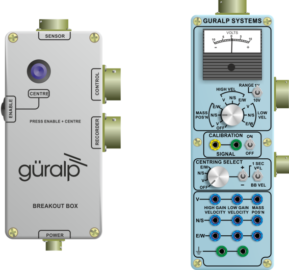
In the illustration above, the break-out box is on the left and the hand-held control unit is on the right.
3.2.2 The hand-held control unit
This portable control unit provides easy access to the seismometer's control commands, as well as displaying the output velocity and mass position (i.e. acceleration) on an analogue meter.
3.2.2.1 Signal meter
The upper section of the HCU contains a simple voltmeter for monitoring various signals from the instrument.
To monitor the low-gain outputs, switch the dial to V, N/S or E/W LOW VEL according to the component you want to monitor.
To monitor the high-gain outputs (on a 40T with that option), switch the dial to V, N/S or E/W HIGH VEL.
To monitor the mass position outputs, switch the dial to V, N/S or E/W MASS POS. Whilst you are adjusting mass position offsets, you should also switch the instrument out of broadband mode by switching the rightmost CENTRING SELECT switch to 1 SEC VEL, or by holding down the CENTRE button on a breakout box.
You can set the range of the meter with the RANGE switch. When switched to 10 V, the meter ranges from –10 to + 10 V (as marked.) When switched to 1 V, the range is –1 to +1 V.
3.2.2.2 Calibration
You can calibrate a 40T sensor through the HCU by connecting a signal generator across the yellow and green CALIBRATION SIGNAL inputs and setting the adjacent switch to ON. The sensor's response can now be monitored or recorded, and calibration calculations carried out. See Chapter 5 for full details.
3.2.2.3 Control commands
If you have ordered a 40T with the remote null facility, you can null its mass position offsets from the HCU.
Select the component you want to centre from the CENTRING SELECT dial.
Switch the signal meter dial to one of the MASS POS settings.
Switch the rightmost switch to 1 SEC VEL to enable the centring lines.
Press the +/– switch towards – to centre a mass from a positive value, or towards + to centre it from a negative value.
3.2.2.4 Banana plugs
The remainder of the HCU provides useful connections for each of the signal lines from the instrument, for attaching to your own equipment as necessary.
3.3 Levelling the instrument
The instrument must be physically level in order to operate correctly.
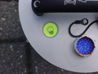
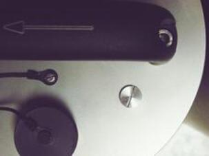
To level the instrument, first check the bubble level on the lid: the bubble should be in the centre of the printed circle. If it is not, loosen the lock-nuts on the instrument’s feet and then adjust the feet until the bubble is central.
Once levelled, secure the feet by screwing the lock-nuts downwards – not upwards – as shown:

3.4 Nulling the instrument
Before installing the 40T, you should check that the mass positions are not significantly offset from zero. The 40T must be perfectly level for this to be effective. The mass position offsets can be affected by any tilt to the instrument as well as rough handling during transportation. The normal range of the mass positions is ±10 V; you should null the offsets of the instrument if any mass reads more than around ±3.5 V (>35% of full scale) when the sensor is level and stationary.
The velocity outputs of the 40T are set at the factory to a nominal value below ±3 mV. Once the instrument is installed and has reached thermal equilibrium with its environment, these outputs should be similar to the factory-set values.
The Güralp 40T can be ordered with a option for automated “digital nulling”. See section 3.4.4 for more information and instructions for using this function.
3.4.1 Adjusting the mass position offsets manually
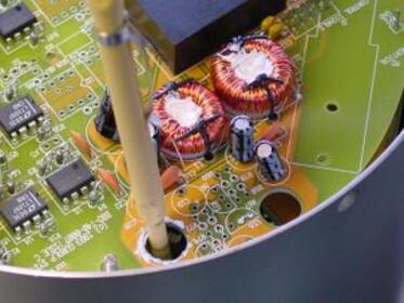
The 40T has three potentiometers (“pots”) accessible within its casing, which should be used to remove any DC offsets electronically:
Bring the instrument into one-second response mode by connecting together the Acc/Vel and Signal Ground pins of the input connector (pins U and Y). If you are using a Hand-held Control Unit, you should select 1 SEC VEL from the Velocity Select switch. Keep the connection or switch in place until you have finished adjusting the instrument.
If you are using a DM24, you can put the instrument into one-second mode by sending a CENTRE command. The effect only lasts for a few seconds in this case so the technique is to make an adjustment, issue the CENTRE command, wait five seconds, check the results and then repeat as necessary.
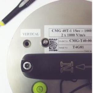
Measure the vertical mass position output with a 10 V voltmeter (see Chapter 6 for pin-out details) or by selecting MASS POS, V from a Hand-held Control Unit's Display Select knob. If using a HCU, also check that the Centring Select knob is set to OFF.
If the vertical component needs adjusting, remove the cap on the lid which protects the Vertical pot with a flat-bladed screwdriver.
Insert the screwdriver through the opening, and engage the pot. An LED flash-light may be useful for locating the head.
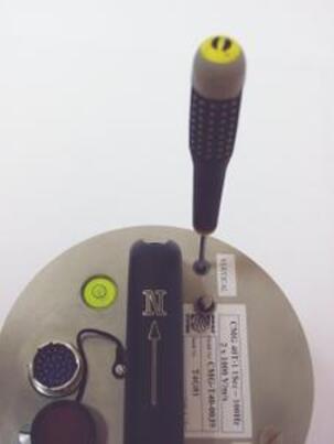
Turn the pot either way until the offset readout is as close to 0 V as possible.
Repeat steps 2 – 5 for the North/South and East/West components.
If the instrument has motor-driven nulling potentiometers, you can adjust them by providing ±5 V voltage to the relevant pin (pin X for vertical, pin V for N/S and pin W for E/W) relative to pin Y (Digital ground/Motor return).
3.4.2 Adjusting the mass position offsets with an HCU
Some 40T units are equipped with a remote mass centring option, which allows you to adjust the internal potentiometers by applying voltages across control lines to the sensor:
Bring the instrument into one-second response mode by selecting 1 SEC VEL from the Velocity Select switch.
Measure the vertical mass position output by selecting MASS POS, V from the Hand-held Control Unit's Display Select knob.
Set the Centring Select knob to V.
Press the spring-loaded switch towards + or – to bring the mass position offset from negative or positive values towards zero.
Repeat steps 3 and 4 for the N/S and E/W components.
Return the instrument to broadband mode by selecting BB VEL from the Velocity Select switch.
3.4.3 Nulling a 40TD digital instrument
The offset potentiometers in a 40TD are in the same place as on the 40T. To access them, you will need to remove the digitiser module, which lies on top of the sensor itself. You can monitor the mass position outputs of the sensor using a Hand-held Control Unit and an adapter cable, available from Güralp Systems.
To change the offsets of a 40TD without digital centring:
Check the bubble level on the lid of the instrument, to ensure it is not tilted. If necessary, re-level the instrument by adjusting its feet. Take care not to disturb the instrument during the subsequent operations.

Unscrew the vent cap on the lid to allow the air pressure to equalise.
Warning: Güralp instruments are assembled at sea level. If working at altitude, there may be a considerable pressure differential. Take care that the vent cap does not “fly off” when released, causing injury.
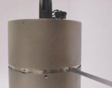
Using a hexagonal wrench, remove the screws holding the digitiser module onto the sensor.
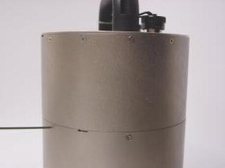
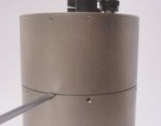
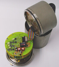
Place a flat-head screwdriver in the notches provided and, holding the bottom part of the instrument steady, twist the screwdriver to lever off the upper digitiser module.
Carefully lift off the digitiser module, and unplug the ribbon cable from the sensor electronics.
Attach a Hand-held Control Unit and adapter cable to the ribbon connector, and power up the sensor through the control unit.
Set the CENTRING SELECT switch on the Hand-held Control Unit to 1 SEC VEL, and the monitoring dial to V MASS POS.
There are three holes in the topmost electronics board, which provide access to the offset potentiometers. Insert a screwdriver through the appropriate hole, and engage the potentiometer for the vertical component.
Adjust the potentiometer until the mass position output reads close to zero.
Repeat steps 4 – 6 for the north/south and east/west components.
Alternatively, you can adjust the mass positions and monitor the output digitally.
Remove the vent cap, and use a hexagon wrench to remove the screws holding the digitiser module onto the sensor as above.
Carefully lift off the digitiser module, and support it nearby, leaving the ribbon cable connected. Extension cables can be obtained from Güralp Systems; otherwise, you can use the casing of the sensor itself as a support.
Whilst monitoring the mass position outputs (channels M8, M9 and MA), adjust the potentiometers as above.
3.4.4 Digital nulling operation
The Güralp 40T sensor can be ordered with an option for automated “Digital nulling”. This removes the need to manually adjust the internal potentiometers to achieve a near zero mass position output for each component. It comprises a micro-controller and three digital potentiometers that replace the standard electromechanical pots.
When installing the instrument, ensure that it is levelled accurately by checking that the bubble in the level lies within the central circle.
On power-up, the micro-controller will automatically null the mass positions of all three axes simultaneously. Nulling can be further triggered via the “centre” control line on pin U. (On instruments without the digital nulling option, grounding pin U (to pin Y) puts the instrument into "one-second mode".)
Automatic nulling takes approximately forty-five seconds to complete, after which the sensor reverts to long period operation and the nulling module enters a low power “sleep” mode. During nulling, the sensor's outputs will fluctuate as the pots are adjusted in a binary search before settling with a mass position of ±0.5V. If the sensor is poorly levelled, the micro-controller will make three attempts to null the mass before giving up and using the closest match.
A test mode is available to check the operation of the digital centring pots. This mode is entered by holding the centre line low during power up. The unit will then set the pots to maximum for thirty seconds; then minimum for thirty seconds; then to the centre position for six minutes. The centre line must be held low continuously, otherwise the unit will abort the test mode and null the sensors as normal.