Chapter 3. Installation
3.1 Unpacking and packing
The 5T Compact accelerometer is delivered in a single cardboard box with foam rubber lining.
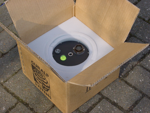
The packaging is specifically designed for the 5T Compact and should be re-used whenever you need to transport the sensor. Please note any damage to the packaging when you receive the equipment and unpack on a clean surface. The package should contain:
the accelerometer,
a signal connection cable (if ordered),
a 26-pin connector (unless fitted to the supplied cable).
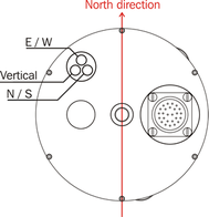
Place the accelerometer on a clean surface and identify:
the signal cable connector on the top of the unit,
the N/S orientation line, engraved on the lid,
the bubble level,
the screw-on cover for the output offset adjuster (see Section 3.4),
the central hole for the main fixing bolt and
the serial number.
If you need to request the sensor production history, you will need to quote either the serial number of the sensor or the works order number, which is also provided on the calibration sheet.
3.2 Initial testing
To test the 5T Compact before installation, you will need a power source which can deliver >100 mA at 10 to 36 V to cover initial transients and a digital voltmeter (DVM) with 1 and 10 V ranges. Also ensure that the supplied cable is connected with the correct polarity.
To make it easier to measure the output from the sensor, you can use a Hand-held Control Unit or an improvised interface box, which can be manufactured from a screw clamp connector block. This will simplify the connections to the appropriate connector pin outputs.
Place the 5T Compact sensor on a flat, horizontal surface.
Connect the power supply, observing the correct polarity for the cable supplied and switch on.
Connect the voltmeter to pins A and B of the output connector (corresponding to the low gain vertical component). Measure the output of the low gain vertical component. The steady output voltage should be about zero (±10 mV).
Repeat the measurement for the N/S and E/W low-gain component outputs (pins C/D and E/F respectively).
Now turn the sensor on its side, propping it carefully to stop it rolling.
The low gain vertical component should now read about –5 V, corresponding to –1 g.
Roll the instrument until the N/S line is vertical, with N at the top.
The low gain N/S component should now read +5 V, corresponding to +1 g.
Roll the instrument until the N/S line is horizontal.
The low gain E/W component should now read +5 V.
If the performance so far has been as expected, the instrument may be assumed to be in working order and you may proceed to install the unit for trial recording tests. In many cases, there will be a slight offset to the readings. This can be compensated for after installation, by adjusting potentiometers (see Section 3.4).
3.3 Installing the sensor
You will need a hard, clean surface such as a concrete floor, to install the 5T Compact.
If you are in any doubt about how to install the sensor, you should contact Güralp Systems.
Prepare the surface by scribing a N/S orientation line and installing a grouted-in fixing bolt on the line, near the middle. A 6 mm (0.25 inch) threaded stud is suitable, as is an expanding-nut rock bolt or anchor terminating in a threaded stud. The bolt should be about 120 mm (5 inches) long.
Place the accelerometer over the fixing bolt and rotate to bring the orientation line and studs accurately into registration with the scribed base-line.
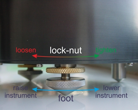
Level the sensor, using its adjustable feet, until the bubble lies entirely within the inner circle of the level indicator.
The feet are mounted on screw threads. To adjust the height of a foot, turn the brass locking nut clockwise to loosen it and rotate the entire foot so that it screws either in or out. When you are happy with the height, tighten the brass locking nut anti-clockwise to secure the foot.
The instrument can use internal simulated level adjustment to compensate for tilt, as long as it is fixed within 1 ° of the horizontal.
Secure the accelerometer in place using a fixing nut with spring washer. Do not screw down the instrument too tightly, as the casing may be deformed.
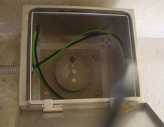 If required, make a screening box for the sensor to shield it from draughts and sharp changes of temperature. A suitable box can be constructed from expanded polystyrene slabs (e.g. 5 cm building insulation slabs) with the joints between them sealed. A hole should be drilled for the connector. You can then use high-grade glass fibre sealing tape to fix the leads in position and to fasten the box securely to the mounting surface. Commercially available duct sealing tape is ideal for this purpose.
Connect the sensor to your digitizing equipment or Hand-held Control Unit to start receiving signals.
3.3.1 Temporary installations
5T Compact sensors are ideal for monitoring vibrations at field sites, owing to their ruggedness, high sensitivity and ease of deployment. Temporary installations will usually be in hand-dug pits or machine-augered holes. Once a level base is made in the floor, the accelerometer can be sited there and covered with a box or bucket. One way to produce a level base is to use a hard-setting liquid:
Prepare a quick-setting cement/sand mixture and pour it into the hole.
“Puddle” the cement by vibrating it until it is fully liquefied, allowing its surface to level out.
Depending on the temperature and type of cement used, the mixture will set over the next 2 to 12 hours.
Install the sensor as above, then cover and back-fill the emplacement with soil, sand, or polystyrene beads.
Cover the hole with a turf-capped board to exclude wind noise and to provide a stable thermal environment.
If you prefer, you can use quicker-setting plaster or polyester mixtures to provide a mounting surface. However, you must take care to prevent the liquid leaking away by “proofing” the hole beforehand. Dental plaster, or similar mixtures, may need reinforcing with sacking or muslin.
3.3.2 Installation in Hazardous environments
The fully enclosed, aluminium case design of the 5T Compact instrument makes it suitable for use in hazardous environments where electrical discharges due to the build up of static charge could lead to the ignition of flammable gasses. To ensure safe operation in these conditions, the metal case of the instrument must be electrically bonded ('earthed') to the structure on which it is mounted, forming a path to safely discharge static charge.
Where electrical bonding ('earthing') is required during the installation of a 5T Compact instrument, the central mounting hole that extends through the instrument should be used as the connection point. This is electrically connected to all other parts of the sensor case. Connection can be made by either a cable from a local earthing point terminated in a 8mm ring tag or by the mounting bolt itself.
3.4 Removing offsets from the 5T Compact
Once installed the sensor needs to be as level as possible to ensure the output offset is minimised. Levelling is carried out by adjusting the feet until the bubble level on the top of the sensor has the bubble completely within the scribed ring.
When power is applied to the 5T Compact, offset adjustments are carried out automatically.
For more information about the effects of offsets and how to avoid them, visit http://www.guralp.com/minimizing-sensor-offsets/.
Should there be a need to reset the offsets, the simplest method is to power cycle the sensor. If this is not possible the following methods can be used.
3.4.1 Manual offset removal
 Early versions of the 5T Compact had a port in the sensor lid to allow for manual offset adjustment. If the sensor has a knurled screw cover then there is a manual offset adjustment option.
Remove the screwed cover protecting the level adjusters. The cavity contains three adjustment screws.
Power up the sensor and connect a digital multimeter to its low-gain vertical outputs (pins A and B). Alternatively, use a Hand-held Control Unit (see Section 3.5, page 13) to monitor the outputs more easily.
Adjust the vertical screw until the output voltage reads zero.
Repeat steps 2 and 3 for the N/S and E/W channels, (with the meter connected across pins C/D and E/F respectively).
If necessary, continue to adjust each channel in turn until consistent results are obtained on all three channels.
Repeat steps 2 to 5 using the high-gain outputs, if available and refine the settings as far as possible. The high gain outputs for the vertical, N/S and E/W channels appear across pins S/T, Z/a and H/K respectively, as shown in section 6.
Ensure that the “O”-ring seal on the adjuster screw cap is present and intact and replace the cap firmly, to keep the instrument's electronics protected from water and dust.
After the cover is installed, the accelerometer outputs may drift until the system establishes temperature equilibrium with its environment and the sensor settles down in its position. If required, the offset adjustment can be repeated to achieve a better output offset. With experience, it should be possible to reduce the output level to less than ±1 mV.
3.4.2 Removing offsets using a terminal connection
Note: this method will only work for the instrument connected to the sensor A port on a digitiser.
Open a terminal window for the required sensor and enter the command:
CENTRE MONITOR
or
CENTER MONITOR
The current offset values will display. Once the process has completed the Scream! status window will display (in green):
CENTERING COMPLETE
Note: if you enter the command CENTRE or CENTER the process will still take place but the mass position values will not display.
3.4.3 Removing offsets using a third party digitisers
To remove offsets while using third party digitisers, connect pin U on the sensor connector to pin Y (see section 6). Note that the sensor must be powered while performing this operation.
The connection between pins U and Y must be maintained for seven seconds before the centring function is activated. The connection must then be released. Centring will continue for as long as is required after the connection is broken,
3.5 The hand-held control unit
| The 5T Compact can be supplied with an optional hand-held control unit (HCU). This is a portable device which provides easy access to the seismometer's controls, as well as displaying the output acceleration on an analogue meter. The 5T Compact uses the same HCU as Güralp 5TB and 40T instruments but there are a few differences. The output from the 5T Compact is acceleration not velocity so, to view the high gain acceleration, select the 'HIGH VEL' switch and to select the low gain acceleration select the 'LOW VEL'. The 5T Compact also doesn't output the mass position and has no electronic centring so these parts of the HCU should be ignored. |
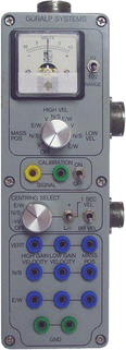
3.5.1 Signal meter
The upper section of the HCU contains a simple voltmeter for monitoring the signals from the instrument.
To monitor the low-gain outputs, switch the dial to V, N/S or E/W LOW VEL according to the component you want to monitor.
To monitor the high-gain outputs, switch the dial to V, N/S or E/W HIGH VEL.
The V, N/S or E/W MASS POS settings are not applicable to 5T instruments.
You can set the range of the meter with the RANGE switch. When switched to 10 V, the meter ranges from –10 to + 10 V (as marked.) When switched to 1 V, the range is –1 to +1 V.
3.5.2 Calibration
You can calibrate a 5T Compact sensor through the HCU by connecting a signal generator across the yellow and green CALIBRATION SIGNAL inputs and setting the adjacent switch to ON. The sensor's response can now be monitored or recorded and calibration calculations carried out. See Chapter 4, page 15, for full details.
When you have finished calibrating, switch the ON/OFF switch back to the OFF position.
3.5.3 Open-loop response
The next section of the HCU contains a dial marked CENTRING SELECT and two switches. The CENTRING SELECT dial and the switch next to it have no effect on 5T Compact instruments: the 1 SEC VEL / BB VEL switch is used to enable open-loop response mode.
To place the instrument in this mode, move the switch to 1 SEC VEL. The feedback loop will be broken, allowing the masses to move freely. To return to normal operation, move the switch back to BB VEL.
3.5.4 Banana sockets
Beneath the CENTRING SELECT dial (which is not applicable to 5T Compact instruments) are connections for each of the signal lines from the instrument, for attaching to your own equipment as necessary.