Chapter 6. ADC configuration
6.1 Introduction
The Güralp Affinity contains one or two ADC cards. Each ADC card provides four full-featured, synchronous ADC channels and a single ADC with an input multiplexor that can handle eight different channels at a lower resolution. Because this style of ADC is unique to the Affinity, its configuration is not covered in the Platinum manual.
6.1.1 Sample rates and decimation
Unlike other Güralp digitisers, the Affinity has a simple decimation model which uniquely maps each output sample rate to a single filter chain configuration. The available output rates (and associated latencies), are shown below:
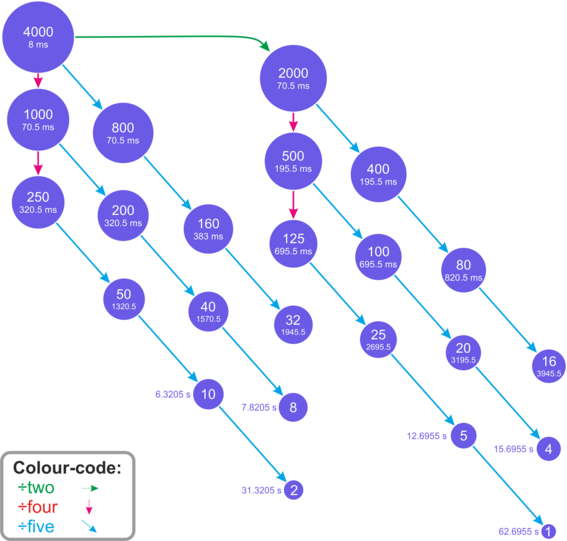
This arrangement offers the lowest possible latency for each output sampling rate without sacrificing quality.
6.2 Data acquisition configuration
The configuration interface can be used to configure the ADC in an Affinity, the digitiser module in a DM24SxEAM or any serially attached Güralp digitiser, such as a Güralp DM24 or CD24, or digital instrument. The interface for external digitisers and digital instruments is described in the Platinum manual. This section describes the interface for the ADC in an Affinity.
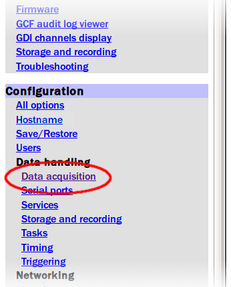
To configure the ADC using the web interface select:
Configuration → Data handling → Data acquisition
If external digitisers and digital instruments are present, a list will be displayed from which you can select the digitiser to configure. If there are no external digitisers, the ADC configuration screen appears immediately.
Note: To control an attached instrument, as opposed to configuring the ADC, please see the Sensor Control section of the Platinum manual.
The first time that this screen is accessed, a warning is displayed:

This is normal and, once a configuration has been saved, it will not be shown again.
The ADC configuration screen has three parts: “Station name/locations”, “Synchronous channels” and “Multiplexed channels”. Each section can be expanded (displayed) or contracted (hidden) by clicking one of the blue arrow symbols,  and
and  .
.
6.2.1 Station name/locations
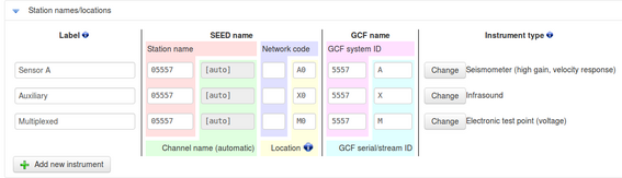
Use this section to configure the logical instruments which are being associated with the ADCs. Each row represents a logical instrument and additional rows can be added as required using the  button.
For each logical instrument, the following attributes are displayed:
SEED name – these values are used for naming channels transmitted over SEEDlink, CD1.1 and some other protocols.
Station name – this is initially based on the serial number of the Affinity but can be altered here as desired.
Channel name – this is automatically determined from the Instrument type
Network code – this can be entered if desired or left blank if not required
Location – this field is automatically populated but can be over-ridden if desired
GCF name – these values are used for naming channels transmitted using GCF protocols, such as Scream and BRP, or GDI.
GCF system ID – this is initially based on the serial number of the Affinity but can be altered here as desired.
GCF serial/stream ID – this field is automatically populated but can be over-ridden if desired
Instrument type – The instrument type can be chosen from the extensive menu which is displayed when you click the
 button. Additional entries may be added by describing the desired instruments in the file /etc/gdi-base/instrument-models.local - contact support@guralp.com for details.
6.2.2 Synchronous channels
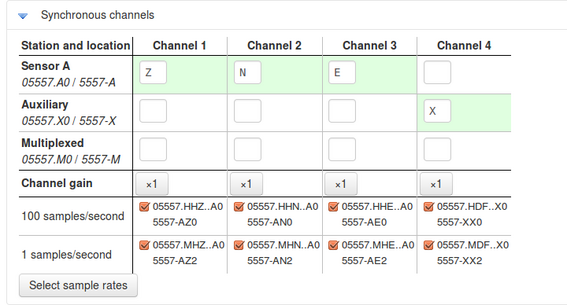
For each of the four main synchronous channels, this section allows you to select the component letter used for stream naming, the Channel gain to be applied and the sample rate(s) to be generated. The default, recommended component lettering for a single triaxial velocity sensor is shown above.
Channel gains from unity to ×64 are available in binary steps. To change a channel gain, click the appropriate  button. The following screen is displayed:
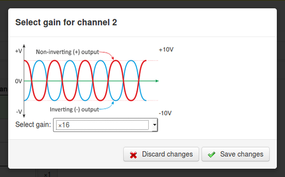
The desired gain can then be selected from the drop-down menu and saved to the configuration with the  button.
One or more sample rates can be selected for each synchronous channel. Each selected sample rate appears in a separate row at the bottom of the table and output from each channel at that sample rate can be enabled or disabled using the check-box.
The automatically-generated SEED names (in S.C.N.L. format) are displayed beside each check-box, above the automatically-generated GCF names.
To add, delete or change the sample rates, click the  button. The following screen is displayed:
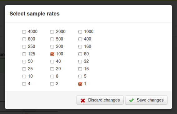
Use the check-boxes to select which sample rates are to be displayed in the main Synchronous channels screen, and then click the
button to return to the main screen.
6.2.3 Multiplexed channels
The Multiplexed channels section displays one row for each available multiplexed channel. The display can be filtered to show subsets of the channels:
The
 button shows only channels designated as mass position channels, typically M1, M2 and M3.
The
 button hides the mass position channels and shows all others.
The
 button displays every channel.
For each multiplexed channel, the associated instrument and component are shown, along with a drop-down menu for selecting the sample rate and the associated automatically-generated SEED name (in S.C.N.L. format) and GCF name.
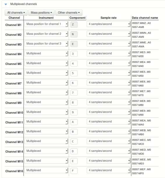
The available sample rates for multiplexed channels are 1, 2, 4, 5, 8 or 10 samples per second. Each channel can also be switched off using the “Sample rate” drop-down menu.
6.2.4 Sensor parameters
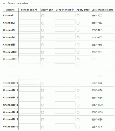
The sensor parameters table is accessed by clicking the link below the multiplexed channels table:

This opens the sensors parameters table, which has one row for each input channel. Each row has:
a field for Sensor gain;
a check-box which controls whether the gain is applied or not;
a field for sensor offset;
a check-box which controls whether the offset is applied or not; and
a label showing the associated output channel name.
Values entered into the Sensor Gain fields will be reported in the associated channel's meta-data as "sensor-gain" or, if applied to the digitiser input before any sensor offset as "sensor-gain-applied". Similarly, values entered into the Offset fields will be reported in meta-data as "sensor-offset" or, if applied to the digitiser input, as "sensor-offset-applied".
Note: Any specified offset is subtracted after the specified gain has been applied.
Data entered into this table are stored in the file /etc/das-in/das-in.local.
6.2.5 Saving and other actions
When all required changes have been made, scroll back to the top of the screen and click the  button. The following screen is displayed:
The configuration is saved and the new settings take effect immediately. Click  to continue. The warning
is removed and not displayed again.
The  button displays the following menu:
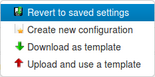
From this menu:
The
 button abandons all changes that have been made to this form since the last save and resets the form to match the saved configuration.
The
 button resets the contents of the form to the factory defaults.
The
 button saves a configuration template file and uses your browser's normal file download facility to allow you to save it to your PC. This feature is intended for use in a future development.
The
 button is currently unimplemented. This feature is intended for use in a future development.