Chapter 4. Installation
4.1 Notes
The goal of any seismic installation is to ensure that wave-trains arriving at the instrument accurately reflect the internal motion of subsurface rock formations. To achieve this, the seismometer and its emplacement need to be considered as a mechanical system, which will have its own vibrational modes and resonances. These frequencies should be raised as high as possible so that they do not interfere with true ground motion: ideally, beyond the range of the instrument.
In particular, the sensor needs to be protected against environmental factors such as
fluctuations in temperature,
turbulent air flow around walls or trees, or around sharp corners or edges in the immediate vicinity of the sensor;
vibration caused by equipment in or near the installation, particularly computer equipment; and
vibration caused by heavy machinery (even at a distance), or by overhead power lines.
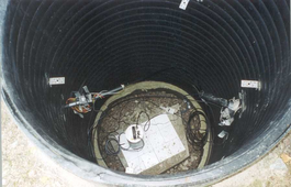
In seismic vaults, instruments are often installed on piers. It is important to ensure that the interface between the pier and the floor does not introduce noise, and that the pier itself does not have resonant frequencies within the passband. Ideally, a seismic pier will be significantly wider than it is high (to minimize flexing) and will form a single piece with the bedrock, e.g. by moulding a poured concrete floor with a wooden frame.
Many situations do not allow for the construction of a seismic vault. For example, you may need to deploy quickly to monitor the activity of a volcano showing signs of rejuvenation, or to study the aftershocks of a major earthquake. Alternatively, the site itself may be too remote to ship in construction equipment.
Temporary installations can be protected against spurious vibrations by
selecting a suitable site,
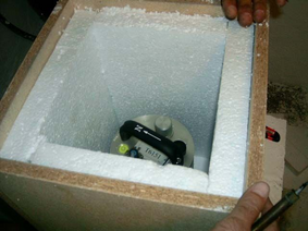
placing the instrument in a protective enclosure (an open-sided box of 5 cm expanded polystyrene slabs, placed over the instrument and taped down to exclude draughts, makes an excellent thermal shield),
standing the sensor on bedrock where possible, or at least deep in well-compacted subsoil;
clearing the floor of the hole of all loose material; and
using as little extra mass as possible in preparing the chamber.
After installation, the instrument case and mounting surface will slowly acclimatise to the local temperature, and settle into their positions. This will take around four hours from the time installation is completed. If you require long-period recording, you should re-centre the instrument after this time.
4.2 Installing in vaults
You can install a 3ESPCD in an existing seismic vault with the following procedure:
Unpack the sensor from its container, saving the shipping box for later transportation.
Prepare the mounting surface, which should be smooth and free of cracks. Remove any loose particles or dust, and any pieces of loose surfacing. This ensures good contact between the instrument's feet and the surface.
If it is not already present, inscribe an accurate North-South line on the mounting surface.
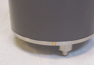
Place the sensor over the scribed line, so that the brass and steel pointers are aligned with the marked directions, with the brass pointer facing North. This can be done by rotating the base of the sensor whilst observing it from above. The brass pointer can be found next to one of the feet.
If you cannot easily see the pointers, you should align the sensor using the north arrow on the handle. However, the alignment of the handle with the sensors inside is less accurate than the metal pointers, so they should be used wherever possible.
The top panel of the 3ESPCD includes a spirit level.
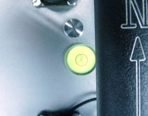
Level the sensor using each of the adjustable feet of the instrument in turn, until the bubble in the spirit level lies entirely within the inner circle. (The instrument can operate with up to 4° of tilt, but with reduced performance.)
The feet are mounted on screw threads. To adjust the height of a foot, turn the brass locking nut anticlockwise to loosen it, and rotate the foot so that it screws either in or out. When you are happy with the height, tighten the brass locking nut clockwise to secure the foot. When locked, the nut should be at the bottom of its travel for optimal noise performance.

Plug the grey/blue power/data cable into the ten-pin connector on the instrument's lid and connect a 12 V power supply to the ends of the grey cable. Connect the DE9 connector to a PC running scream, using a USB-to-RS232 converter, if required.
Note: GSL strongly recommend USB/RS232 converters based on the FTDI chip-set. Numerous problems have been found with converters based on the other common chip-set.
Alternatively, connect the ten-pin connector on the instrument's lid to an EAM using cable CAS-DCM-0001 (green).
Plug in the GPS cable and connect the GPS receiver.
In Scream's set-up dialogue, select the “COM Ports” tab and set the Baud rate of the appropriate COM port to 38,400 Baud. Click OK and wait for the instrument to appear in Scream's source tree.
Right-click on the digitiser's entry in the source tree and select Control.... Click on the Mass control tab, followed by Unlock. (If the Mass control tab is unavailable, check the sensor type in the Sensor type tab, apply, and open a new Control window.)
Alternatively, if you are using an EAM, navigate to the Control → Instruments, select the correct instrument from the drop-down menu and click on the
 button.
Caution: After this point, you should be careful not to tilt the instrument or you may damage it.
Right-click on the digitiser's entry in Scream's source tree and select Control.... Click on the Mass control tab, followed by Centre.
Alternatively, if you are using an EAM, navigate to the Control → Instruments, select the correct instrument from the drop-down menu and click on the
 button.
Monitor the mass positions during the centring operation. You may need to initiate several rounds of centring before the mass positions reach an acceptable value. ±
Cover the instrument with thermal insulation, for example, a 5 cm expanded polystyrene box. This will shield it from thermal fluctuations and convection currents in the vault. It also helps to stratify the air in the seismometer package. Position the thermal insulation carefully so that it does not touch the sensor package.
Ensure that the cables are loose and that they exit the seismometer enclosure at the base of the instrument. This will prevent vibrations from being inadvertently transmitted along the cables.
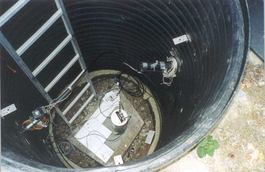
4.3 Installing in pits
For outdoor installations, high-quality results can be obtained by constructing a seismic pit.
Depending on the time and resources available, this type of installation can suit all kinds of deployment, from rapid temporary installations to medium-term telemetered stations.
Ideally, the sensor should rest directly on the bedrock for maximum coupling to surface movements. However, if bedrock cannot be reached, good results can be obtained by placing the sensor on a granite pier on a bed of dry sand.
Prepare a hole of 60 – 90 cm depth to compacted subsoil, or down to the bedrock if possible.
On granite or other hard bedrock, use an angle grinder to plane off the bedrock at the pit bottom so that it is flat and level. Stand the instrument directly on the bedrock, and go to step 6.
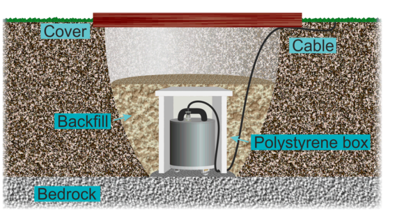
On soft bedrock or subsoil, you should install a pier as depicted below:
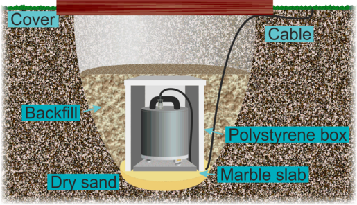
Pour a layer of loose, fine sand into the pit to cover the base. The type of sand used for children's sand-pits is ideal, since the grains are clean, dry and within a small size range. On top of the sand, place a smooth, flat marble or granite plinth around 20 cm across, and shift it to compact the sand and provide a near-level surface.
Placing a granite plinth on a sand layer increases the contact between the ground and the plinth, and improves the performance of the instrument. There is also no need to mix concrete or to wait for it to set, as in step 4.
Alternatively, if time allows and granite is not available, prepare a concrete mix with sand and fine grit, and pour it into the hole. Agitate (“puddle”) it whilst still liquid, to allow it to flow out and form a level surface, then leave to set. Follow on from step 6.
Puddled concrete produces a fine-textured, level floor, ensuring optimal coupling for the seismometer. However, once set hard, the concrete does not have the best possible coupling to the subsoil or bedrock, which has some leeway to shift or settle beneath it.
Alternatively, for the most rapid installation, place loose soil over the bottom of the pit, and compact it with a flat stone. Place the seismometer on top of this stone. This method emulates that in step 3, but can be performed on-site with no additional equipment.
Set up the instrument as described in Section 4.2.
The instrument must now be shielded from air currents and temperature fluctuations. This is best done by covering it with a thermal shield.
An open-sided box of 5 cm expanded polystyrene slabs is recommended. If using a seismic plinth on sand (from steps 3–4 or 5), ensure that the box is firmly placed in the sand, without touching the plinth at any point. In other situations, tape the box down to the surface to exclude draughts.
Alternatively, if a box is not available, cover the instrument with fine sand up to the top.
The sand insulates the instrument and protects it from thermal fluctuations, as well as minimizing unwanted vibration.
Ensure that the sensor cable is loose and that it exits the seismometer enclosure at the base of the instrument. This will prevent vibrations from being inadvertently transmitted along the cable.
Cover the pit with a wooden lid, and back-fill with fresh turf.
4.4 Rapid installations
This section details a method of deploying 3ESPCD instruments with the minimum of additional equipment. This is recommended for situations where seismic instrumentation needs to be installed very quickly, e.g. to study a resumption of volcanic activity, or where difficulty of access to the site prevents you from constructing a full seismic pit. You should always construct a pit if possible (see Section 4.3), since the data produced will be of significantly higher quality.
4.4.1 Deployment
Prepare a hole of 60 – 90 cm depth to compacted subsoil, or down to the bedrock if possible.
Clean the hole down to the bottom, and remove any loose material from the mouth. Ensure that the bottom of the hole is relatively flat.
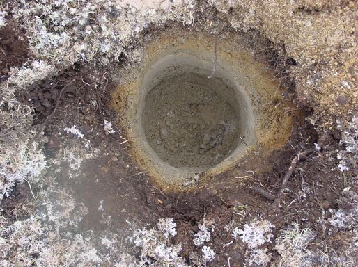 9
9If the bottom of the hole is made of hard rock, you may need to put in some loose sand or soil so that the sensor can be levelled.
Connect the sensor to cables for the GPS unit and power source.
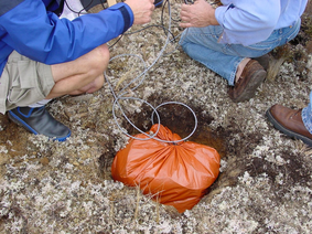
Carefully insert the instrument into the hole, protected by a tough plastic bag to keep water out. Use a bag strong enough to bear the weight of the sensor and breakout box, so that it can be recovered easily.
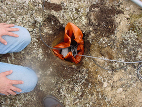
Press the sensor down firmly into the soil, without tapping or hitting it.
Check the bubble level on top of the instrument package. Adjust the instrument's position if necessary so that the bubble lies entirely within the black circle.
Pack soil or sand around the instrument to hold it steady. Make sure the soil or sand is firmly compacted and not at all loose.
Recheck the bubble level. If you cannot adjust the soil packing at this stage and the sensor is not level, you will need to clear the hole and restart from step 3.
Power the sensor and connect it to a laptop. Unlock the masses using Scream's Control window.
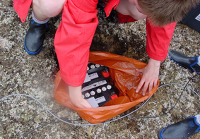
Place the breakout box and any excess cable on top of the sensor, inside the plastic bag.
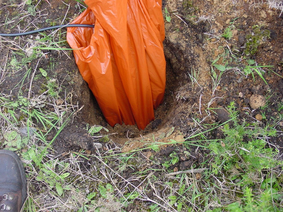
Group the cables coming from the bag for a distance of about 1 m, and keep them together with insulating tape.
Tie the top of the package and fold it over so that water cannot get in. Leave any excess cable within the bag.
Cover the installation with soil or sand until it is no longer visible.
Attach a GPS unit to the cable coming from the sensor. Seal the connection between the data cable and the GPS unit's IEEE 1394 cable inside a plastic bag to protect it from moisture.
Position the GPS unit so that it has a good view of the sky. Bury the cable and connector package so that they cannot be seen.
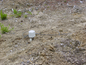
If possible, place the GPS near the instrument so that it can be found more easily, and the connector package near the GPS so you can retrieve data from the instrument without affecting the installation.
If you are using a battery as a power source, dig a second hole for it. This hole does not need to be as deep as the pit for the instrument—perhaps 10 cm plus the height of the battery.
Attach the sensor power cable to the battery, and wrap it in another plastic bag. Place the bag in the hole.
Tie the bag and fold over, to make the battery as waterproof as possible.
Bury the power cable between the battery and the instrument, and compact soil or sand around the bag.
Fill in and cover the hole so that it is not visible.
4.4.2 Recovery
Care should be taken when recovering the 3ESPCD, since tapping or banging it can cause damage to the sensors inside. The following instructions assume that you have installed the instrument following the steps above.
Find the GPS receiver, which will be the only feature visible from the surface, and follow the buried data cable from it to the instrument.
Carefully remove earth from the hole until you find the power cable coming from the instrument.
Follow the power cable to the battery pit, and carefully dig away the soil to reveal the battery about 10 cm from the surface.
Connect a laptop to the data connector and, using Scream's Control dialogue, lock the masses.
Disconnect the power cable from the battery. (With the power off, the sensor is less likely to suffer electrical damage during recovery.)
Return to the location of the sensor, and dig down to it. You should be able to remove a spade's head depth of soil without hitting the instrument. Beyond that, using a small hand shovel, follow the wires and carefully remove the remaining soil until you can see the plastic bag. Take special care not to damage the wires, which should be tied together in the vicinity of the bag.
Carry on removing soil, either with your hands or (very carefully!) with the shovel, until the whole bag is uncovered to about half the height of the instrument.
If the hole is relatively dry, open the bag and lift the instrument out by its handle.
Caution: Do not lift the instrument by any of the attached cables. Straining the cables may result in invisible damage, making future installations unreliable.
Alternatively, if the hole is waterlogged, carefully lift out the entire bag in one piece, and remove the contents at the surface.
4.5 Installing in post-holes
The 3ESPCD is suitable for installation in potholes. In soft subsoil, a hole between two and four metres deep and 200 mm wide can be conveniently excavated using a tractor-mounted or hand-operated pothole auger. To minimize surface effects, you should ensure that the hole is at least 1 metre deeper than the length of the instrument, and preferably somewhat more.
Since the hole has no lining, it may occasionally flood. However, most soil types are sufficiently permeable to allow water to soak away, leaving the packing material moist.
To install a 3ESPCD in a pothole:
Clean the pothole, making sure there is no loose material around the mouth of the hole or on its base.
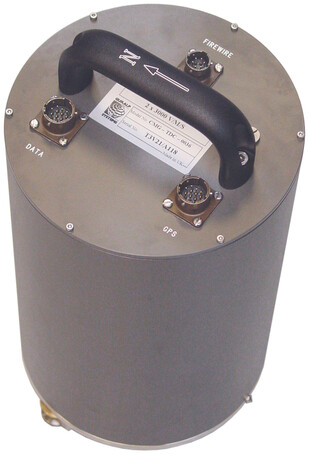
Prepare the instrument package, making sure the inclinometer is visible, and attach it to a winch or hoist by clamping a light steel cable to the centre of the handle so that the package hangs vertically. Connect the signal cable to the instrument.
Add packing material to the hole to about 150 mm depth. Fine crushed rock, with a high proportion of rock flour and fine particles, makes excellent packing material. Alternatively, a mixture of 3 mm grade angular coarse grit with around 30% medium grit gives good results. Moisten the packing material in the hole and ram firm.
Lower the instrument to the bottom of the hole, but without slackening the lifting cable.
Fill more packing material around the instrument for about 30 cm, moisten, and ram firm.
Use the bubble level to check that the instrument remains within its tilt tolerance (± 2 °).
Continue filling, moistening and packing until the instrument is buried, checking that the tilt remains within tolerance.
Release the strain on the lifting cable, and allow the packing material to settle for 24 hours.
If all is well after the settling period, release the lifting tackle, coil a tail of the lifting wire into the top of the hole and backfill almost to the surface.
Ensure that the cable is slack, and fix it to a support at the top of the hole.
Ram a split wooden bung into the top of the hole, and cover with sandbags.
Attach the signal cable to your laptop. Power the sensor, and unlock it. Carry out preliminary tests using Scream!, if required.
4.6 Other installation methods
The recommended installation methods have been extensively tested in a wide range of situations. However, past practice in seismometer installation has varied widely.
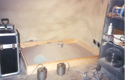
Some installations introduce a layer of ceramic tiles between a rock or concrete plinth and the seismometer, as shown in the left-hand picture below:
However, noise tests show that this method of installation is significantly inferior to the same concrete plinth with the tiles removed (right). Horizontal sensors show shifting due to moisture trapped between the concrete and tiling, whilst the vertical sensors show “pings” as the tile settles.
Other installations have been attempted with the instrument encased in plaster of Paris, or some other hard-setting compound (left):
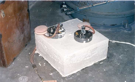
 Again, this method produces inferior bonding to the instrument, and moisture becomes trapped between the hard surfaces. We recommend the use of fine dry sand (right) contained in a box if necessary, which can also insulate the instrument against convection currents and temperature changes. Sand has the further advantage of being very easy to install, requiring no preparation.
Finally, many pit installations have a large space around the seismometer, covered with a wooden roof. Large air-filled cavities are susceptible to currents which produce lower-frequency vibrations, and sharp edges and corners can give rise to turbulence. We recommend that a wooden box is placed around the sensor to protect it from these currents. The emplacement may then be backfilled with fresh turf to insulate it from vibrations at the surface, or simply roofed as before.
By following these guidelines, you will ensure that your seismic installation is ready to produce the highest quality data.
4.7 Networking overview
The 3ESPCD can optionally be supplied with no networking, with a wired Ethernet connection or with both wired and wireless Ethernet connections.
For wired-only units, the networking capabilities are provided by an embedded Lantronix WiPort-NR module.
For wireless-equipped units, the networking capabilities are provided by an embedded Lantronix WiPort module.
Additional information about both modules is obtainable from Lantronix's web-site: www.lantronix.com.
The Lantronix modules are both twin-channel serial-to-TCP converters. Channel one's serial interface is exposed on the instrument's main connector; this can be used to provide networking capabilities to any external device with an RS232-compatible output. Channel two is internally connected to the standard digitiser output using an internal RS-232 link.
Note: If a serial device (such as Scream or a terminal emulator) is detected on the DATA port (via the break-out box), the networking module is automatically disconnected. Hence, networking is only available when the DATA port is disconnected.
Note: Note that the wired and wireless capabilities of the WiPort are also mutually exclusive: only one can be active at a time and, indeed, the wireless interface cannot even be configured when the device is in wired mode.
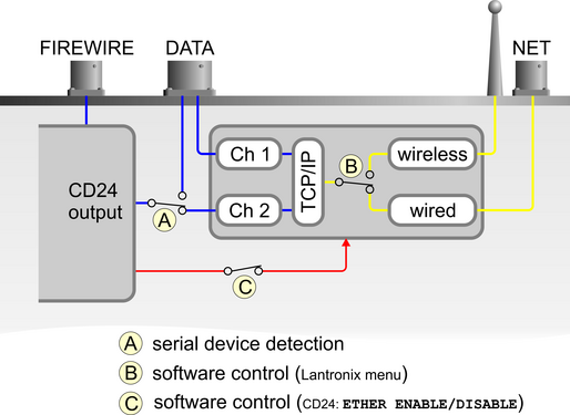
The illustration above shows serial data in blue, network data in yellow and power connections in red.
The Lantronix module can be powered down with the CD24 command
ETHER DISABLE
and powered up with the command
ETHER ENABLE
Certain operations, such as a firmware upgrade, can result in power to the Lantronix module being turned off. In these cases, the ETHER ENABLE command should be used to restore power.
4.8 Setting up the Ethernet interface
3ESPCD instruments with Ethernet features installed use an embedded Lantronix WiPort-NR module to provide the network interface. This module can be configured using a built-in Web server.
Before you can access the Web server, however, you will need to assign the device an IP address. This can be done using Lantronix' DeviceInstaller utility for Microsoft Windows, or using a DHCP server. You will need a PC with a network interface installed.
4.8.1 Using DeviceInstaller
Download and install the DeviceInstaller utility from the Lantronix Web site at http://www.lantronix.com/.
DeviceInstaller also requires the Microsoft .NET framework to be installed. If you do not have this already, it can be downloaded at http://www.microsoft.com/.
Find out the MAC address of the 3ESPCD's network interface. This should be printed on a label on the case.
If the Data Out port on the breakout box is connected to anything, disconnect it.
Connect the 3ESPCD's ETHERNET port to the the PC's network interface, either using a crossover Ethernet cable or through a network hub.
Using a hub, you can connect several 3ESPCDs to the same PC and configure them all at the same time.
DeviceInstaller will not work through routers or across the Internet. All the devices need to be on the same network segment as the PC.
Run DeviceInstaller.
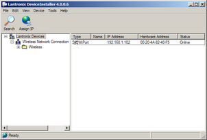
DeviceInstaller's main window has two panels, a tree on the left (with Lantronix Devices at the top) and a table on the right.
The program will automatically look for Lantronix devices on all of your computer's network interfaces. If necessary, you can narrow the selection by clicking on an entry in the tree on the left.
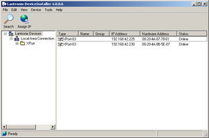
A WiPort-NR entry should appear in the table on the right, denoting that a device has been detected.
If more than one WiPort entry appears, DeviceInstaller has detected several devices.
For every detected device, the program shows the Hardware Address (i.e. the MAC address), and the IP address it is currently using. If your local network uses a DHCP server, the device will ask the DHCP server to assign it an address. Otherwise, a random address will be chosen automatically.
Automatic random addresses all begin with 169.254. The 3ESPCD will choose a different one every time it is power-cycled or rebooted.
The address of the 3ESPCD may be shown in red with the status Unreachable. If this happens, the sensor and PC cannot communicate because they are not on the same subnet.
Click Assign IP (
 ) to start the IP configuration wizard.
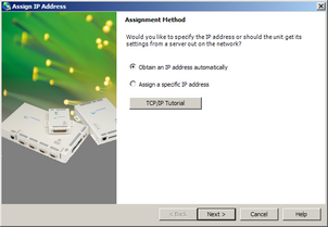
Follow the instructions in the wizard to set the IP address, or configure DHCP if you are using a DHCP server.
Once set, click Search (
 ) to find the sensor with its new address.
If you want to configure the 3ESPCD to use a static IP address, use the Assign IP wizard as above, and click Search again.
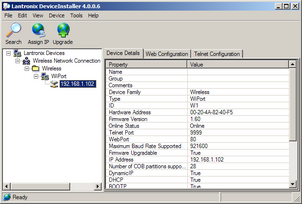
Double-click on the entry which corresponds to the 3ESPCD you want to configure.
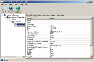
The right-hand panel will change to show the current properties of the device.
Switch to the Web Configuration tab, and click Go (
 ) to open the Web configuration interface.
Alternatively, click Use External Browser (
 ) to use your own Web browser to configure the instrument.
In either case, unless you have previously configured password protection, simply click
 if prompted for a user name and password.
Follow the steps in section 4.8.3 to configure the module from its Web interface.
4.8.2 Using DHCP
If you cannot install DeviceInstaller on your PC, or do not wish to, you can also get access to the 3ESPCD using a standard DHCP server. In most cases you will need to have administrative privileges to do this.
Install and start the DHCP service on your PC.
Connect the 3ESPCD's ETHERNET port to the the PC's network interface, either using a crossover Ethernet cable or through a network hub.
Using a hub, you can connect several 3ESPCDs to the same PC and configure them all at the same time.
DHCP will not work through routers or across the Internet. All the devices need to be on the same network segment as the PC.
Monitor the DHCP server to find out what IP address it gives to each instrument.
To configure a device, enter its IP address into a web browser. Unless you have previously configured password protection, simply click
if prompted for a username and password.
4.8.3 Configuration with the Web interface
Once you have access to the WiPort-NR's Web interface, you can configure it with its proper settings. Unless you have previously configured password protection, simply click
if prompted for a user name and password.
The Web page is divided into three. A menu on the left switches between pages of configuration options on the right. There is also a banner at the top, which tells you the current firmware revision and the MAC address.
To navigate around the Web site, click on the entries in the left-hand menu. When you have made changes to the settings on any page, save them by clicking
before you leave the page.The WiPort-NR has two serial channels which you can connect to. By default these are exposed on ports 10,001 and 10,002.
Channel 1 (normally port 10,001) is connected to a serial console which is exposed on the instrument's main connector. If you have problems connecting to the 3ESPCD over a network, you can attach a diagnostics cable, CAS-PEP-0041, to this port and use Scream! to access the console.
Channel 2 (port 10,002) is connected to the 3ESPCD's digital output, unless you have connected a serial data cable from the breakout box to a computer. If the breakout box is connected, the 3ESPCD will send data streams through that interface rather than to the WiPort-NR.
Click on Channel 2 – Serial Settings.
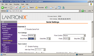
Set the Baud Rate to 19200. This is the default baud rate for the 3ESPCD's digital output.
Note: If you change the baud rate in Scream! or using the terminal, you must come back to this page and change the Baud Rate setting.
The remaining settings can be left at their default values. Click
to save your changes.For full information on the WiPort-NR's configuration options, please refer to the WiPort documentation, which is available on the Lantronix Web site, http://www.lantronix.com/.
When you have finished setting up the WiPort-NR, apply the new settings by clicking
 . The WiPort-NR will re-boot with the new settings in effect.
Note: Simply changing settings in the web page and clicking does not effect any functional change. You must click before the changes take effect.
If the WiPort-NR is using an automatically chosen random IP (beginning with 169.254), the IP address will change when you do this. You will need to go back to DeviceInstaller to find out the new IP address.
4.9 Setting up wireless networking
3ESPCD instruments with wireless features installed use an embedded Lantronix WiPort module to provide the network interface. This module can be configured using the DeviceInstaller utility for Microsoft Windows, or using a DHCP server. You will need a PC with a wireless card installed.
You may find it easiest to gather together all the Wi-Fi hardware before taking it into the field, and configuring it from a local wireless-enabled PC.
3ESPCD instruments with the wireless networking option also have an ETHERNET port for attaching to a wired network. You can switch between the wired and wireless interfaces using DeviceInstaller.
Note: There are two types of wireless network topology supported by the WiPort, infrastructure and ad-hoc. GSL can only support 3ESPCDs running in infrastructure mode.
4.9.1 Using DeviceInstaller
Download and install the DeviceInstaller utility from the Lantronix Web site at http://www.lantronix.com/.
DeviceInstaller also requires the Microsoft .NET framework to be installed. If you do not have this already, it can be downloaded at http://www.microsoft.com/.
Find out the MAC address of the 3ESPCD's network interface. This should be printed on a label on the case.
Configure your wireless router or access point to use a network name (SSID) of LTRX_IBSS
Disable any security features of the wireless router or access point.
Run DeviceInstaller. The main window has two panels, a tree on the left (with Lantronix Devices at the top) and a table on the right.
The program will automatically look for Lantronix devices on all of your computer's network interfaces. If necessary, you can narrow the selection by clicking on an entry in the tree on the left.
A WiPort entry should appear in the table on the right, denoting that a device has been detected.
If more than one WiPort entry appears, DeviceInstaller has detected several devices.
For every detected device, the program shows the Hardware Address (i.e. the MAC address), and the IP address it is currently using. If you are using a wireless router with a DHCP server, or an access point connected to a network with a DHCP server, the device will use DHCP to assign it an address. Otherwise, a random address will be chosen automatically.
Automatic random addresses all begin with 169.254. The 3ESPCD will choose a different one every time it is power cycled or rebooted.
The address of the 3ESPCD may be shown in red with the status Unreachable.
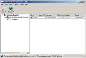
If this happens, the sensor and PC cannot communicate because they are not on the same subnet.
Click Assign IP (
) to start the IP configuration wizard.Follow the instructions in the wizard to set the IP address, or configure DHCP if you are using a DHCP server.
Once set, click Search (
) to find the sensor's new IP address.If you want to configure the 3ESPCD to use a static IP address, use the Assign IP wizard as above, and click Search again.
Double-click on the entry which corresponds to the 3ESPCD you want to configure.
The right-hand panel will change to show the current properties of the device.
Switch to the Web Configuration tab, and click Go (
) to open the Web configuration interface.Alternatively, click Use External Browser (
) to use your own Web browser to configure the instrument.In either case, unless you have previously configured password protection, simply click
if prompted for a username and password.Follow the steps in section 4.9.3 to configure the module from its Web interface.
4.9.2 Using DHCP
If you cannot install DeviceInstaller on your PC, or do not wish to, you can also get access to the 3ESPCD using a standard DHCP server. In most cases you will need to have administrative privileges to do this.
Install and start the DHCP service on your PC.
Configure your wireless router or access point to use a network name (SSID) of LTRX_IBSS
Disable any security features of the wireless router or access point.
Monitor the DHCP server to find out what IP address it gives to each WiPort in range. If necessary, power cycle the sensor(s).
To configure a device, enter its IP address into a web browser. Unless you have previously configured password protection, simply click
if prompted for a username and password.
4.9.3 Configuration with the Web interface
Once you have access to the WiPort's Web interface, you can configure it with its proper settings. Unless you have previously configured password protection, simply click
if prompted for a user name and password.
The Web page is divided into three. A menu on the left switches between pages of configuration options on the right. There is also a banner at the top, which tells you the current firmware revision and the MAC address.
To navigate around the Web site, click on the entries in the left-hand menu. When you have made changes to the settings on any page, save them by clicking OK before you leave the page.
Click on WLAN (Wireless Local Area Network) to open the WLAN Settings page.
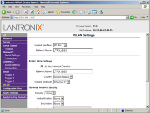
Change the Network Name (i.e. SSID) from LTRX_IBSS to a suitable name for your installation. This name will be announced to any nearby wireless devices when they search for networks.
Make a note of the SSID that you have used.
Under Wireless Network Security, set Security to WEP and configure the security parameters. If you do not do this, anyone will be able to access the 3ESPCD and change its configuration.
Make a note of the security parameters you have used.
Click OK, followed by Apply Settings in the main menu. The WiPort will restart.
If the WiPort is still using an automatically chosen random IP (beginning with 169.254), the IP address will change when you do this. You will need to go back to DeviceInstaller to find out the new IP address.
Configure your wireless access point or router to use the new name and security settings, and power cycle the 3ESPCD to make it reconnect to the network.
Reconnect your computer to the wireless network using the new name and security settings.
The WiPort has two serial channels which you can connect to. By default these are exposed on ports 10,001 and 10,002.
Channel 1 (normally port 10,001) is connected to a serial console which is exposed on the instrument's main connector. If you have problems connecting to the 3ESPCD over a network, you can attach a diagnostics cable, CAS-PEP-0041, to this port and use Scream! to access the console.
Channel 2 (normally port 10,002) is connected to the 3ESPCD's digital output, unless you have connected a serial data cable from the breakout box to a computer. If the breakout box is connected, the 3ESPCD will send data streams through that interface rather than to the WiPort.
Click on Channel 2 – Serial Settings.
Set the Baud Rate to 19200. This is the default baud rate for the 3ESPCD's digital output. If you change the baud rate in Scream! or using the terminal, you must come back to this page and change the Baud Rate setting.
The remaining settings can be left at their default values. Click
to save your changes.For full information on the WiPort's configuration options, please refer to the WiPort documentation, which is available on the Lantronix Web site, http://www.lantronix.com/.
When you have finished setting up the WiPort, apply the new settings by clicking
. The WiPort will re-boot with the new settings in effect.Note: Simply changing settings in the web page and clicking does not effect any functional change. You must click before the changes take effect.
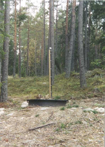
4.9.4 Installing wireless hardware
The small antenna supplied with the 3ESPCD is adequate for initial testing or temporary installations with an access point within 50 metres of the instrument.
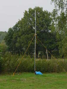
To send data over a larger distance, or if the line of sight between the antenna and the access point is blocked, you will need to use a larger antenna.
You can reduce the power requirements by using a directional antenna pointed at the location of the access point. The access point does not need to be permanently present. For example, you could set up an array of 3ESPCD instruments with antennas pointed towards a prominent natural feature with a direct line of sight to all the instruments, and access them all from this location using a laptop PC.