Chapter 2. Installing the CMG-DCM
2.1 Overview
The DCM is effectively a low-power Linux computer dedicated to seismic data flow tasks. Resources permitting, the DCM can perform any computational task you require. Because of this flexibility, the DCM must be configured for your particular purposes before it can be used:
-
If you only need to use the DCM as a data store, you can gain console access over the serial port for configuration.
-
If you are going to use the DCM as part of a TCP/IP network, you must set up its IP address and other networking parameters before you can connect to it. Whilst the network is inoperative, you will need to connect to the DCM console over a direct serial connection. We recommend that you configure the DCM correctly, to the best of your knowledge, before shipping it into the field.
-
If you want to connect to the DCM using TCP/IP over modem links, you must set up PPP over these links. Configuring PPP is beyond the scope of this manual: please see the Linux man page for ppp for details, or the Linux PPP HOWTO.
-
Once communication with the DCM is working, you should set up the serial ports on the DCM to provide the services you require.
-
When all ports are configured, you can use the DCM to set up attached Güralp digitizers and digital instruments.
2.2 Power supply
The stand-alone DCM receives its power from lines in its data connectors. All three of these ports are Güralp standard 10-pin combined serial/power interfaces. Cables are available from Güralp Systems which enable you to connect a 9-pin D serial interface and 2-way power connector to any of these ports.
You can power the DCM from whichever data port is most convenient, whether or not it is being used for receiving or transmitting data. However, you should always supply power to the DATA OUT plug if possible, since it is easy to accidentally short the pins of a male connector. Attached digitizers and sensors are powered from the same supply as the DCM. Any 12 V DC power supply may be used; if using batteries, we recommend that you use a unit with low-voltage disconnect to avoid excessive drain.
A rack-mounted DCM has a separate POWER IN connector on the back panel, which should be attached to a 12 V DC supply. There is also a POWER OUT connector on this panel, which allows you to daisy-chain several DCM units together. The POWER OUT connector is provided merely for convenience: lines from the POWER IN connector pass straight through.
An integrated DCM receives its 12 V DC power from two pins in its single connector. See Chapter 9, page 127, for the positions of these pins.
2.3 Connecting to a single computer
In autonomous or temporary installations, you will only need to connect the DCM to one computer (e.g. a laptop) for initial configuration. Follow these instructions to make the DCM communicate with your computer.
Note that your computer must either have an RS232 (serial) port for initial connection, or be running its own DHCP server. DHCP servers are available for Windows, but are not supplied as standard.
If you want to connect the DCM to a local area network, follow the instructions in Section 2.4, page 15, instead.
The DATA OUT port can be used to connect a DCM to a single computer through a direct serial link. This link can be used to log in to the Linux operating system of the DCM and transfer files. It is most useful for maintenance and troubleshooting over a low-bandwidth connection, and for initial setup.
To communicate over a serial link:
-
Connect an RS232 reverse serial cable between the DCM and your computer. A suitable cable should have been supplied with the unit.
-
Run a terminal emulation program on the computer. The built-in programs minicom for Linux, and hypertrm for Microsoft Windows, can be used for this.
-
Configure the baud rate of the serial link. By default, the DCM uses a baud rate of 115200, with 8 data bits, no parity bit, and one stop bit, and without flow control.
-
Log in with your username and password, or root if you have not yet created one. See http://www.faqs.org/docs/Linux-HOWTO/Text-Terminal-HOWTO.html for full information on how to set up terminal emulation under Linux.
-
You now have access to the DCM's console and all of its functions. You should change your password, if you have not done so already, with the command passwd
For full details on how you can configure the serial ports of the DCM, see Section 6.2, page 82.
You can use a “crossover” Ethernet cable to connect the DCM directly to your computer. This has the same effect as connecting the DCM and your computer to a separate hub using standard Ethernet cables: the two machines will consitute a network segment, and each will have its own IP address on that segment. See Section 2.4, page 15, for details on how to configure TCP/IP on the DCM.
If your computer has two network interfaces, and one is connected to a local area network, you may be able to set up a network bridge between the DCM's segment and the rest of the network. For example, if you are using Microsoft Windows XP:
-
Connect to the DCM's console over a serial link.
-
Because you are connecting the DCM to a single computer, you will probably not be able to use DHCP. You should configure the DCM to disable DHCP and use an IP address in a private range such as 192.168.0.x:
gcfgdbset net.eth.0 static
gcfgdbset net.eth.0.address 192.168.0.2
gcfgdbset net.eth.0.netmask 255.255.255.0
Here, 192.168.0.2 should be replaced with the IP address you want the DCM to use.
Allow a short time for the DCM to reconfigure the network.
-
On your computer, select Start → Control Panel → Network Connections. Right-click on the interface connected to the DCM, and select Properties.
-
Click on Internet Protocol (TCP/IP), then Properties.
-
Select Use the following IP address, and fill in an address on the same subnet as the DCM (e.g. 192.168.0.49). Click OK, then OK in the Connection Properties window.
-
Check that you can connect to the DCM using its new IP address by opening its Web site at
http://192.168.0.2/
-
Advanced usage: If you later want to connect your computer to a local area network, you can make the DCM visible to that network by setting up a network bridge. Before doing this, you must make sure that the IP addresses you have chosen for the DCM and your computer are suitable for the local network you want to connect it to.
To set up the bridge, open the Network Connections window, and select the connections corresponding to the DCM and your network. Click Bridge connections, and follow the instructions in the wizard.
If you are using Linux or another operating system, you should see its own documentation for more details.
If you have ordered a DCM with an internal PCMCIA modem, it will automatically listen for incoming PPP connections. This is most useful if the DCM is integrated into a borehole instrument, which can then be connected to a modem at a central data collection point. The modem within the DCM appears on the Web configuration interface as a serial port, allowing you to change the service it provides and the data transfer settings it uses. For example, if you do not want the internal modem to use PPP, you can configure it to use mgetty instead and log in directly.
If your DCM is equipped with the USB client interface, you can connect it directly to any computer with a USB socket. When this is done, the computer treats the module as if it were a standard network card. For example, to connect the DCM to a PC running Microsoft Windows, you should:
-
Link the DCM's USB port to any available USB socket on the computer.
-
After a short wait, Windows should report that a new USB device has been detected. When prompted to install drivers for it, you should use the ones provided on CD by Güralp Systems.
Once the “network card” is installed, the two machines form a network segment, and each one has its own IP address on that segment. See the next section for details on how to configure TCP/IP on the DCM. If you wish, you can set up a network bridge between this connection and a local area network or the Internet as described above.
2.4 Connecting to a local network
The DCM is normally supplied with a 10BaseT Ethernet port. This port can be used to connect to your local network.
When the DCM starts up, it will try to find a DHCP server on your network to assign it an IP address.
If you use DHCP on your network, and you want to access the DCM's Web server or console over the network, you may be able to find out from the DHCP server which address it has given the DCM, in which case you can access it directly. Otherwise, you will need to connect to the DCM over a serial link to find out its IP address.
If you do not use DHCP on your network, you will have to set the DCM to use a static IP address.
-
Make a temporary serial connection to the DCM from a local PC. You should see the message
DCM login:
-
Enter root and the administrator password. If you have not been given a password, the default setting is rootme. The DCM will reply with a prompt:
[root@DCM ~]#
This verifies that the unit is working properly. You should change the password as soon as you can with the command passwd
-
Connect the DCM's NETWORK port to your network, and power cycle it. Log in again.
-
If your network does not use DHCP, type
gcfgdbset net.eth.0 static
to make the DCM use a static IP address instead, and set the address with
gcfgdbset net.eth.0.netmask 255.255.255.0
gcfgdbset net.eth.0.address your-address
Here, your-address should be replaced with the IP address you want the DCM to use. The IP address you choose must be unique on your network.
If you are connecting the DCM to a machine on the same network, you do not need to configure any more options at this stage.
If your network uses DHCP, you will not need to perform this step. Instead, ensure the DCM is also using DHCP with
gcfgdbset net.eth.0 dhcp/bootp
-
Issue the command ifconfig
The DCM will reply with technical information on its current network setup. Each interface is listed separately. The NETWORK port uses the interface eth0:
eth0 Link encap:Ethernet HWaddr 08:00:20:C0:FF:E2
inet addr:192.168.48.187 Bcast:192.168.48.255 Mask:255.255.255.0
UP BROADCAST NOTRAILERS RUNNING MULTICAST MTU:1500 Metric:1
RX packets:88045 errors:36 dropped:0 overruns:36 frame:0
TX packets:16308 errors:0 dropped:0 overruns:0 carrier:0
collisions:149 txqueuelen:100
RX bytes:12358214 (11.7 MiB) TX bytes:0 (0.0 B)
Interrupt:76
If the interface is correctly set up, its IP address will be shown after inet addr: (here, 192.168.48.187.)
-
If you are connecting the DCM to a single computer which does not run a DHCP server, you will need to configure that computer to use an IP address on the same subnet as the DCM before they will be able to reach each other (see “Connecting over Ethernet“ on page 13.)
You should now be able to connect to the DCM's Web setup interface by typing its IP address into any browser, e.g.
https://192.168.0.2/
Scream! and similar software applications should also be configured to use this address to communicate with the module, if they are intended to communicate over the network.
Alternatively, you can continue using the gcfgdbset command to set other configuration options by name. In Chapter 6, each option's name is given in italics. The command syntax to use is
gcfgdbset option-name new-value
The options will take effect immediately whenever possible. Some changes may take some time to complete, since services may need to be restarted. The gcfgdbset command performs only simple checks on the new value, so you should check the syntax of the option carefully.
Optionally, a DCM may be supplied with 802.11 (“Wi-Fi”) hardware in place of Ethernet. There are two modes in which an 802.11 network may operate:
-
In ad hoc mode, data packets are sent out over the wireless connection indiscriminately and are received by all machines on the network. This is the simplest style of Wi-Fi network, but consumes more power and cannot easily be extended to large networks.
-
In infrastructure mode, dedicated 802.11 hubs collect data packets, collate, and distribute them efficiently around the network. These hubs may also act as transparent extensions to existing (wired) TCP/IP networks.
The DCM is capable of running in either situation, depending on your requirements. As far as the computers on the network are concerned, there is no difference between a TCP/IP network running over Ethernet and one using 802.11 connections, or a mixture of the two.
Once the 802.11 system is running, you will need to run a DHCP service on your network, or manually set the IP address of the DCM as above.
If the local network is already connected to the Internet through some other means (perhaps through a gateway machine), you can create a default route with
gcfgdbset net.eth.0.gateway network-gateway
where network-gateway should be replaced with the IP address of the gateway on your local network.
The DCM can perform more complex routeing if required. See “Static routes”, page 80, for more details.
As supplied, the DCM module will accept requests to its on-board Web server and logins over SSH. In addition, the DCM can be requested by Scream! or other GCF-compatible software to send GCF streams to your computer.
If the instrument is located on a private network, you may be able to connect to it from the wider Internet by using a feature implemented by SSH known as tunnelling. You can use this technique to connect to the DCM through a chain of intermediate machines which support SSH. Once this chain is set up, you can treat the connection as if it were a direct link between the DCM and your computer. Many standard Internet protocols may be fed through SSH in this manner. Whether this is possible will depend on the precise configuration of your local area network. For more details, please see the documentation for SSH clients such as ssh and putty.
2.5 Connecting digitizers and external hardware
The DCM is designed for use with Güralp Systems digitizers, which communicate over RS232 or RS422 serial links using the GCF protocol. There are three RS232 ports available on a stand-alone DCM and ten on a rack-mounted model, whilst on a DCM bonded to a digitizer unit only the DATA OUT port is available (the digitizer is connected directly to the PORT A interface).
The three serial ports on a stand-alone DCM are labelled DATA OUT, PORT A, and PORT B. In a typical setup, one or both of the latter two ports are connected to Güralp DM-24 digitizers, whilst the DATA OUT port connects the DCM to a computer or serial modem. However, the labels are provided merely for convenience: internally all three serial ports behave identically. Thus, if the DCM is connected to a network over Ethernet, you could use all three ports to communicate with digitizers. Conversely, if you have only one digitizer attached to a stand-alone DCM, either or both of the remaining two ports could be used to transmit data gathered by the module.
A rack-mounted DCM has a CONSOLE port with a female connector, corresponding to the Data out port of the stand-alone model, and nine serial ports (with male connectors) for communication with digitizers.
If the DCM has a USB host interface, you can connect it to any USB peripheral supported by its Linux operating system. For example, you may want to attach a camera to the DCM, or an additional USB mass storage device. If there is no hard disk inside the module, it will automatically search for suitable storage on the USB interface. The DCM may alternatively have been supplied as a USB client; if this is the case, the USB connection can be used to connect the module to a single computer (see below).
2.6 Setting up the DCM
Once a DCM is installed, it must be configured to your particular requirements. The easiest way to set up a DCM is through its on-board Web server, which gives you access to all the module's configuration options. You can use this Web interface over any network connection using the HTTP or HTTPS protocols. Alternatively, you can log in to the DCM's Linux operating system and issue commands directly: see Section 8.2, page 117.
The DCM provides a Web interface which you can use to set up the system. To access this from anywhere on the local network, open any web browser and navigate to the IP address of the DCM. For example, if the DCM has the address 10.82.0.1 you would enter
http://10.82.0.1/ or https://10.82.0.1/
https is a secure variant of the http protocol, which ensures that network traffic cannot be read in transit. The DCM as supplied accepts connections only over https, although this may be altered if required (see “HTTP server”, page 79.)
Your browser may ask you for a username and password to access the Web configuration interface. An initial root username and password will have been supplied by Güralp Systems; however, you should check with the DCM's administrator what username you should use. On a clean install of the Linux distribution, the password for root is rootme.
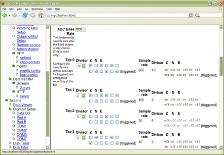
Once you have logged in, you will see a Web page similar to this:

The work area on the right displays a summary table describing the current setup of the DCM's serial ports, and showing how many blocks of data have been received on each one.
Under the Configure heading are two links for each serial port. Port provide quick access to the DCM's configuration settings for the port, and Digitizer allows you to configure a Güralp Systems digitizer attached to the port REFERENCE???
Scrolling down in this window, you will see
-
a list of all the files currently stored in the on-board Flash memory, with a link to download each one;
-
a summary of the current status of the DCM's removeable hard disk;
-
the status of the tamper-proofing subsystem (used mainly on integrated DCMs and AMs; standard DCMs do not have the tamper lines exposed, so you can ignore this section);
-
the current Linux network and DNS configuration;
-
unique IDs for the hardware boards making up the DCM; and
-
the name and version number of every software package currently installed on the unit.
The links in the menu on the left lead to various pages where you can change the configuration of the DCM.
As a first step, you change your administrator password. Scroll down the left-hand menu if necessary, and click on Configuration – Administrators.

At the bottom of this page is a section headed Existing users. In this section, enter your new password in the password and repeat password boxes, and click Change password.
If you want to add any other named accounts, you can do this on the same page (see “”, page .)
Next, you should configure the DCM and attached digitizers for your own needs. Several pages of configuration options are available under Configuration in the left-hand menu. When you make changes to any page, make sure you click the Save changes button at the bottom of the page before you move to a new page.
Examples of how to configure a DCM for several common applications are given in the next chapter, whilst a full reference is provided in Chapter 6. Some important points to note are:
-
The DCM uses internal serial and Ethernet ports to communicate with the digitizer and the network. Altering the serial or network settings may make the instrument unreachable over the network. You should review carefully any changes you make to these settings before committing them.
-
It is possible to disable the DCM's ssh, http, and https servers using the links under Data transfer. Before doing this, you should ensure that you will still have access to the DCM by other means, e.g. by logging in directly over ssh.
Configuring digitizers with the DCM
You can change the configuration of attached DM24 digitizers through the DCM's web page interface. To do this, click on one of the Digitizer links beneath Configure in the serial port table.
The DCM will then retrieve the current configuration from the DM24, which will take a few seconds. This done, a page will appear allowing you to alter the digitizer's settings:

You can change all of the digitizer's configuration options from this page. If you have attached a 6-channel digitizer, the page will reflect this:
When you are done, click Configure instrument to submit the changes to the digitizer and reboot it.
See “Digitizer output control”, page 107, for full details of what you can do.
Configuring digitizers with Scream!
If you prefer, you can use Güralp Systems' Scream! software to configure and calibrate digitizers and sensors through the DCM module. You can do this either over the network, or using a serial port.
To connect over the network, start the DCM's Scream! server (see ???REFERNECE) and connect to the DCM using Scream!'s Network Control window. The digitizer should appear under an entry for the DCM in Scream!'s main window.
To connect over a serial link, set the service for the serial port to gcf_out (see ???REFERENCE), and connect the serial port to your computer. The digitizer should appear in Scream!'s main window. The DCM may not appear in this case, because it does not send its own GCF blocks.
For full details on how to use Scream!, please refer to its own documentation or the extensive on-line help.