Chapter 3. The CD1.1 modules
This section of the manual will describe the function of each of the four CD1.1 modules in detail. For precise configuration instructions, please refer to sections 5 through 8.
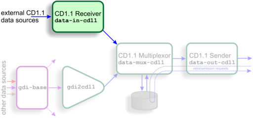
3.1 The CD1.1 multiplexor (data-mux-cd11)
This is the central store-and-forward module for CD1.1 subframes. Every CD1.1 configuration requires at least one CD1.1 multiplexor instance to be active. An instance of this module must be configured before the configuration system will allow any other CD1.1 modules to be instantiated.
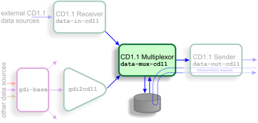
CD1.1 subframes originating from either external CD1.1 sources (via data-in-cd11) or from non-CD1.1 sources (via gdi2cd11) are transmitted to this module. The multiplexor stores these subframes, either on disk or in flash RAM, and will coalesces frames from multiple sources where this is appropriate. It then forwards complete data frames onwards to the output stage, data-out-cd11.
Subframes are stored briefly before they are assembled into frames. There is a trade-off between the data latency - the amount of time between a subframe's reception and its transmission as part of a frame - and the overall framing efficiency - the number of subframes that can be packed into a single frame. A parametrised algorithm is used to allow the operator to tune this to suit each application's specific requirements - see section 3.1.1 for more details.
The multiplexor is responsible for responding to retransmission requests arriving from external receivers via a data-out-cd11 instance. The subframe store is used to satisfy these requests. An interactive logging tool is provided to allow the operator to query and inspect the contents of the store.
One storage file is created per day. To limit the amount of back-fill being stored, a directory cleaner task must be set up to remove unwanted storage files.
3.1.1 Frame assembly time-outs
Two separate time-out parameters are used to control the assembly of related subframes into frames: one for real-time data and one for back-filled data.
In complex networks, data may arrive from a number of CD1.1 data producers (DPs) along diverse routes, each with different transmission latencies. DPs may be added and removed at any time and communications may be interrupted for short or long periods. A dropped link or a decommissioned station should not interrupt the flow of data from other stations. Because of this, the frame assembly algorithm does not and, indeed, cannot know how many subframes it should expect for any given time-stamp. It is therefore necessary to use time-outs when assembling subframes into frames.
As an example, let us consider a hypothetical array with three remote sensor stations functioning as CD1.1 DPs, all of which use ten-second subframes, and a central data consolidation station. The transmission times of the three links to the central station are, say, one, two and three seconds. The real-time data time-out at the central station will be set to three seconds.
At some time, T0, each station begins assembling samples into subframes and, at around T0 + 10 seconds, they all transmit their completed subframes to the station. Each subframe is labelled with the time-stamp of its first sample: T0.
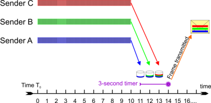
At T0 + 11 seconds, the first subframe arrives at the station. The multiplexer inspects the time-stamp and, as it has not seen any subframes labelled T0 before, it stores the subframe in a new collection, labelled T0, and sets an alarm (specific to this collection) for the current time (T0 + 11) plus the time-out - i.e. T0 + 14 seconds.
At T0 + 12 seconds, the second subframe arrives at the station. The multiplexer inspects the time-stamp and places the subframe in the existing T0 collection. At T0 + 13 seconds, the third subframe arrives and is treated identically. At this point, the multiplexer does not know that it has received all the subframes, so it carries on waiting.
At T0 + 14 seconds, the alarm for this collection fires and the multiplexer assembles all the subframes from the T0 collection into a frame and passes it to the data-out-cd11 module(s). The collection is moved to the data store and is no longer considered active.
Now consider the case where the third communication link is interrupted for, say, five seconds, starting at T0 + 10. The first and second subframes will arrive as before and, at T0 + 14 seconds, they will be assembled into a frame and transmitted.
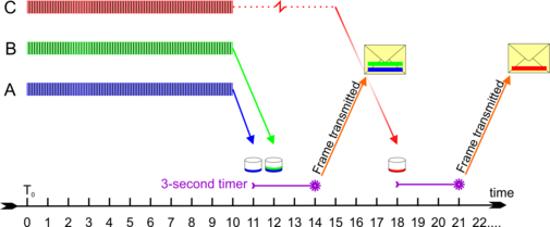
One second later, at T0 + 15 seconds, the link is restored and the third subframe is transmitted. It will arrive at T0 + 18 seconds. The multiplexer inspects the time-stamp and, as it has no longer has an active collection labelled T0, it stores the subframe in a new collection, also labelled T0, and sets an alarm (specific to this collection) for the current time (T0 + 18 seconds) plus the time-out - i.e. T0 + 21 seconds. No more packets labelled T0 will arrive so, when the alarm fires, the lone subframe will be wrapped up as a frame and transmitted on its own.
If the time-out had been set to eight seconds, the delayed subframe would have arrived in time to be sent along with the other two: the packing efficiency would have been improved but, as the completed frame would not have been transmitted until T0 + 19 seconds, the overall latency would have increased. The time-out should thus be adjusted to achieve the desired trade-off between subframe packing efficiency and overall data latency.
Where back-filled subframes are involved, it is assumed that latency is of lesser concern - the data are already significantly delayed - and packing efficiency is considered more important. For this reason, although the algorithm is identical, a separately configurable time-out is provided which only applies to back-fill frames. It is expected that this time-out will normally be set to a significantly higher value than the live data time-out.
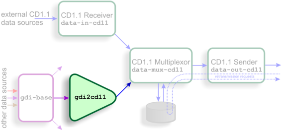
3.2 The GDI to CD1.1 converter (gdi2cd11)
This module is used to encode data from non-CD1.1 sources into standards-compliant CD1.1 subframes. It should be used, for example, when data from directly attached digitisers and digital instruments are to be transmitted using CD1.1.
The subframes contain a number of additional data beside the samples:
Channel meta-data is used to populate the “instrument type” and “gain” fields
The “channel status” field is populated using information from the state-of-health data provided by gdi-base, from the anti-tamper lines (and other digital input/output fields) and from the internal temperature and voltage monitoring subsystems.
Optionally, a cryptographic signature generated by a hardware engine (such as the Spyrus encryption card). Operation of such hardware is discussed in chapter 11.
The subframes can support any sample rate and can be of various durations (in multiples of 10 seconds).
3.2.1 Channel Subframe Status Field
The gdi2cd11 module implements the first permitted status field as defined with format value = 1 in the CTBTO standard revision 0.2. There are several reserved bits and bytes in the standard, and these can optionally be mapped to additional details in the gdi2cd11 configuration (see section 6.2.4).
The meaning of the bits is mapped as follows (counting from 1, with 1 being the least significant bit and 8 the most):
Byte(s) | Bit(s) | Description | Mapping |
2 | 1 | Dead sensor channel | Not used |
2 | Zeroed data | Not used | |
3 | Clipped | Not used | |
4 | Calibration under way | Set when calibration is in progress on associated component | |
3 | 1 | Equipment housing open | Configurable tamper monitor |
2 | Digitiser open | Configurable tamper monitor | |
3 | Vault door opened | Configurable tamper monitor | |
4 | Authentication seal broken | Configurable tamper monitor | |
5 | Equipment moved | Configurable tamper monitor | |
6–8 | Future use | Configurable tamper monitors | |
4 | 1 | Clock diff. too large | Set if clock difference ≥±1000µs (configurable) |
2 | GNSS receiver off | Set if ADC module reports no communication from GNSS, or GPS power is off | |
3 | GNSS receiver unlocked | Set if ADC module reports clock is not phase locked to GNSS PPS signal | |
4 | analogue input shorted | Not used | |
5 | Calibration loop back | Not used | |
6–8 | Future use | Not used | |
5 | 1 | Main power failure | Configurable; set if voltage of chosen line drops below specified value |
2 | Backup power unstable | Configurable; set if voltage of chosen line drops below specified value (independent from main power failure bit) | |
3–8 | Future use | Not used | |
6 | 1–8 | Undefined | Configurable; 8-bit voltage, temperature, power or current reading #1 |
7 | 1–8 | Undefined | Configurable; 8-bit voltage, temperature, power or current reading #2 |
8 | 1–8 | Undefined | Configurable; 8-bit voltage, temperature, power or current reading #3 |
9–28 | Time of last GNSS synchronisation | Most recent reported lock from ADC module, invalid (< year 2000) if never locked. | |
29–32 | Clock differential in microseconds | If clock is locked, this is the measured difference between the ADC's sample clock and the GNSS PPS line in µs. If unlocked, it is an estimate (magnitude, so always positive) of the drift based on the measured worst-case drift of the ADC's crystal. |
Bytes 6, 7 and 8 of the status field can optionally be used to monitor line voltage, power or current flow, or temperature. As there are only 8 bits available, the scales for the value are complex and must be manually configured by the operator in order to get the best range available. Values that are outside what can be represented are clipped at 0 or 255 (not aliased).
The voltage scale allows a value between 5.0 and 30.5 to be represented with 0.1 increments. To convert from the unsigned byte value x to an analogue value, use:

The power or temperature scale allows a value between -64 and 63.5 to be represented with 0.5 increments. Note that EAM modules measure incoming power as positive, and outgoing power as negative. To convert from the signed byte value x to an analogue value, use:

To convert from the unsigned byte value u to an analogue value, use:

The current scale allows a value between -1.28 and 1.27 to be represented with 0.01 increments. Note that EAM modules measure incoming current as positive, and outgoing current as negative. To convert from the signed byte value x to an analogue value, use:

To convert from the unsigned byte value u to an analogue value, use:

3.3 The CD1.1 receiver (data-in-cd11)
This module receives CD1.1 frames from external CD1.1 senders (DPs). It is typically used at an array data centre, where it receives data frames from any CD1.1 senders in the array; typically each array element or station will have its own CD1.1 sender.
The receiver is fully standards-compliant, although it has no support for validating incoming signatures.
The receiver can accept connections and data from multiple, simultaneous, remote DPs. It correctly identifies and requests re-transmission of missing data frames by issuing CD1.1 acknack frames.
Note: Unlike other Platinum data reception modules, the CD1.1 receiver module does not currently alter or decode any subframes it receives and it does not pass them to gdi-base: they are passed on unaltered and only to the CD1.1 multiplexor module.
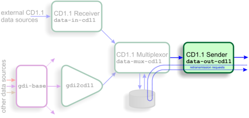
3.4 The CD1.1 sender (data-out-cd11)
This module is a fully standards-compliant CD1.1 sender (DP). It is responsible for:
Receiving CD1.1 channel subframes from the multiplexor;
Assembling them into full CD1.1 frames;
Transmitting them over a TCP network to a remote receiver (DC);
Handling retransmission requests originating from its clients;
Monitoring the transmission log to determine whether any gaps have occurred (for example, due to re-starting of the sender process) and, if so, transmitting the missing packets (back-fill);
Logging all transmissions to a “frame list” held on local disk or Flash memory; and, optionally,
Digitally signing the frames using an optional hardware encryption engine (see chapter 11).
A CD1.1 sender module can only transmit to a single Data Consumer (DC). If there is a requirement to support multiple DCs, multiple sender module instances are needed. Each can send a different set of subframes, if required.
Because the multiplexer supports multiple senders, it is more efficient for transmitted frames to be stored by the multiplexer, rather than by the sender. This avoids having to store the same frame multiple times. However, because the frame numbering of outgoing frames is connection specific, the multiplexer cannot know these numbers and it stores frames by time-stamp, rather than by frame number. The sender keeps track of which frame is which by storing a database of frame numbers against timestamps. This database is consulted when the sender receives an acknack frame, so that it can request the correct frame from the multiplexer by quoting the time-stamp.
It also handles back-fill over extended periods of outage by recording which times the system was down, and requesting the data once the link is established again - a process known as back-fill. The order in which back-fill data are transmitted is configurable: it can either be “first-in, first-out” (FIFO) or “last-in, first-out” (LIFO).