Chapter 8. Using the CD1.1 Sender
This module is responsible for receiving subframes from the multiplexor, assembling them into full CD1.1 frames, transmitting them to a remote receiver (and logging the transmissions), handling back-fill, satisfying retransmission requests and digitally signing frames.
Note that the CD1.1 sender module does not require or verify authentication data on frames it receives from the Data Consumer (DC).
On start-up, the sender attempts to connect to the DC. The DC responds to the connection request with a redirection notification, which contains an I.P. address and port number, to which the sender is required to re-connect. Progress in connecting (including the redirected address) will be logged via syslog (i.e. into /var/log/messages) or to the configured log-file. Once connected, the sender waits for sets of subframes from the CD1.1 multiplexor and sends them as a packaged frame to the DC. After sending each frame, if the TCP output buffer is empty, the sender will check for any outstanding back-fill and, if required, transmit a back-filled frame.
8.1 Back-filling and retransmission
Back-fill occurs if the sender is disconnected from the DC for a period of time. Retransmission occurs if the DC sends an acknack frame detailing one or more gaps in its reception record.
Whenever a real-time (i.e. not back-filled) data frame is transmitted, its time-stamp is recorded in a database. If this time-stamp does not match the previously- recorded time-stamp plus the subframe duration, a back-fill gap is noted in this database file. This allows the output module to be turned off, or to crash, while ensuring that gaps are still recorded. It also deals with the situation where a connection to the DC becomes unavailable; once the connection is re-established, the first frame to be transmitted will cause the output module to realise there is a gap and it can then be back-filled correctly.
In this context, transmission counts as the frame being written to the TCP socket correctly, and does not take into account whether the DC has successfully received the frame. If the DC does miss the frame due to, say a lost packet on the network link, it will be recovered and retransmitted later when the DC sends an acknack frame.
Whenever any frame is transmitted, it is assigned a sequential sequence number. A second database file, the framedb, records the sequence numbers against the time-stamps of the frames being transmitted. The DC periodically produces an acknack frame which indicates which of those frames have been successfully received; once a frame has been acknowledged, it is purged from the frame database file.
If the acknack frame indicates that the DC has a gap, the frame database file is consulted to find the time-stamp of the missed frame(s), and those frames are added to the list for retransmission.
Tools are provided to maintain the two database files. See Section 10.2 for more details.
8.2 Creating a new CD1.1 sender instance
In the web interface, select “Configuration -> Services” from the left-hand menu or from the command line, run
gconfig
and then select “System services”.
Now choose “data-out-cd11 -- CD1.1 sender” to view a list of configured sender instances. You can choose to either configure any existing instance (as described in the following section) or select “Create new service instance” to create a new one.
A form is displayed which allows you to set various parameters for the instance. The default values are suitable for most applications but each parameter is discussed in the following section. After entering the desired configuration for the instance, click  to save your changes.
This will create (if it is new) and configure the sender instance. If it is not already running, you can start it by using “Control -> Services” on the web menu or by running
/etc/init.local/data-out-cd11.0 start
from the command line.
The zero after the period in the command name determines which sender instance is to be started, so the command to start a second instance would be
/etc/init.local/data-out-cd11.1 start
8.3 Configuration options for the sender
The configuration screen for the receiver has two tabs: General and Senders.
8.3.1 The General tab
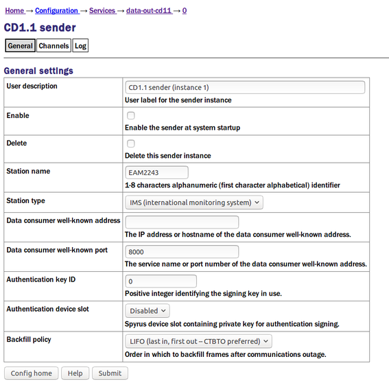
The User description is an alternative, human-readable label for this instance. It is used, for example, in log files. If you are building a complex application with several senders, you should set this to something which describes the function of this particular instance. In most cases, this can be left at the default setting.
The Enable check-box controls whether this instance is to be automatically started each time the system boots or whether it should be left to be started manually.
The Delete check-box, if ticked, will cause this instance to be deleted when the form is submitted.
The Station name field identifies this sender instance to communicating Data Consumers (DCs), according to the CD1.1 protocol. This name should be unique and is normally set using the system's hostname. The station name field is also used as the “frame creator” for frameset naming.
The Station type drop-down menu is also used to identify the sender in connection request frames. It can be set to “IMS (international monitoring system)”, “NDC (national data centre)” or “IDC (international data centre)”.
The Data consumer well-known address field should be populated with the I.P. address or DNS name of the DC (receiver) to which frames should be sent. If a name is used, it is first looked up in the standard Linux /etc/hosts file; if no match is found, the configured DNS server is queried.
The Data consumer well-known port field should be populated with the port (service) number or name to which frames should be sent at the DC. If a name is used, it is looked up in the standard Linux /etc/services file.
Note that these two fields only specify the “well-known DC address”; as part of the connection establishment, the receiving system will redirect the sender to another port/address. The redirection will be logged via the configured logging mechanism (syslog or file).
The Spyrus card used for checking signatures can store nineteen different key-pairs and the Spyrus card slot drop-down menu selects which is to be used. If the sender should not sign packets, this can be left set to “disabled”.
The Authentication key ID field sets a flag in the CD1.1 header which some customers use to identify which encryption key pair (from a pre-defined set) has been used. It is generally set to be the serial number of the signing certificate and should be set to zero if signing is not used.
The Backfill policy drop-down menu controls the order in which requested back-fill frames are transmitted. The options are “LIFO (last in, first out -- CTBTO preferred)” and “FIFO (first in, first out -- time series)”.
8.3.2 The Channels tab
The next section of the configuration screen is the Channels table, which controls channel filtering: i.e. which channels are to be transmitted by this sender instance. The on-screen text explains its use.
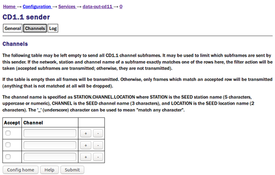
To transmit all but a few channels, list the channels to omit and leave the Accept check-boxes clear (not ticked).
To transmit only a few channels, list the channels to send, tick their Accept check-boxes and, as the final line, enter the wild-card sequence:

with the check-box clear (not ticked). (The above line contains five underscores, a period, three underscores, a period and two underscores, with no spaces.)
The underscore character matches any single character. Some further examples of filter rows follow.
To make a filter row which rejects all subframes from the station TEST, enter a filter row with the Accept check-box clear (not ticked) and a Channel field of “
 ”.
”.To make a filter row which rejects all subframes from vertical channels, enter a filter row with the Accept check-box clear (not ticked) and a Channel field of “
 ”.
”.To make a filter row which matches only broadband, high-gain channels, enter a filter row with the Accept check-box ticked and a Channel field of ”
 ”.
”.
Combining filter rows allows you to build a complete filter. For example, to make the sender only send broadband, high-gain channels (but not from the TEST station), you would use this filter:
Row 1: Accept not ticked, Channel “
”Row 2: Accept ticked, Channel “
”Row 3: Accept not ticked, Channel “
”
In this example:
The first row rejects all channels from the TEST station.
Unmatched channels (i.e. those from another station) will continue to the second row, which accepts any channel whose name starts BH (regardless of component). Channels which do not match continue to the third row, which simply rejects everything else.
Clicking the
 button on any row will open a new row. In the same way, rows can be deleted by clicking the corresponding
  button.
8.3.3 The Log tab
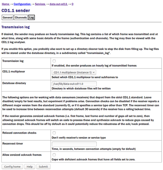
The first check-box enables or disables the Transmission log, which is described in the on-screen text.
Caution: If the Transmission log is enabled, large files will accumulate in the log directory which, if not managed, will cause the system to run out of secondary storage (flash or hard disk space), causing the system to crash. Because of this: (a) you should ensure that you have sufficient space available to store the expected amount of data; and (b) you should configure a directory cleaner to remove unwanted files from this directory (see Section 9.1 for more details).
The sender takes its input from an instance of data-mux-cd11. In most applications, there will be only one instance of this and the CD1.1 multiplexor field can be left at its default value. When building more complex configurations, it may be necessary to have more than one instance of the multiplexor. This fields lets you select, for the sender, which instance of data-mux-cd11 to use for input. All configured instances appear on the associated drop-down menu.
The Database directory field controls where the transmission log files, as described above, are stored. These may be stored on additional flash memory, if fitted: See Section 14 for more details. Setting up a directory cleaner, as recommended in the on-screen text, is described in Section 9.1.
The three final controls allow interoperation with data consumers that depart from the strict CD1.1 standard. They can normally be left disabled/empty but, if problems arise, please contact support@guralp.com to discuss whether these options can help.