Chapter 4. Operation Guide
4.1 Principals of operation
The Strong Motion Display is a touch-screen PC pre-configured to run three software packages: Güralp Systems' real-time monitoring and acquisition software, Scream!, the strong-motion packet import application, gdi-sm-app, and seismicmonitor.exe, which provides the user display, monitors thresholds and triggers alarms as appropriate. The seismicmonitor.exe package receives data in UDP packets from Scream! and the strong-motion packet import app using the software IP loopback adapter.
In order to use the system, Scream! and the strong-motion packet import app must first be configured to receive strong motion data from a digitiser or digital instrument. Multiple digitisers may be connected and configured but seismicmonitor.exe will only monitor one at a time.
Scream! is used for receiving GCF data from serial or network sources that use the BRP protocol or the Scream protocol. The strong-motion packet import app is used for receiving data in GDI format over the gdi-link protocol.
4.2 Configuring the strong motion data display
Connect the various components of the system together, as described in Section 3.3, connect the keyboard/mouse 'Y'-cable to the keyboard/mouse connector on the side of the unit (see Section 5.1.1), connect a standard PC keyboard and mouse to the 'Y'-cable (purple for the keyboard, green for the mouse), apply power and allow the system to boot.
The first time the system boots, it will not have any data sources configured and no System ID will be displayed at the top of the screen.
4.2.1 Creating InfoBlocks
In order to correctly compute the strong motion results, the digitiser requires calibration information about both itself and the sensor to be uploaded in small text file called an InfoBlock. InfoBlocks are prepared using notepad.exe and uploaded to the digitiser using Scream!.
Before you can prepare an InfoBlock, you need to obtain calibration information for both the sensor and the digitiser. Calibration sheets will have been delivered with the units but, if they have been mislaid, they can be retrieved from Güralp System's automatic calibration document service. To use this service, simply send an email to caldoc@guralp.com with the subject line containing the serial number of the instrument you wish to retrieve the calibration document for.
You can retrieve as many documents as necessary by specifying multiple serial numbers on the subject line, separated by spaces. If you have an instrument with an integrated digitiser, or a digitiser with an integrated acquisition unit, it will have several serial numbers separated by a forward-slash (‘/’). In these cases, replace the forward-slash(es) with spaces./
For example, if you have a Güralp 3TD with serial number T3A15/D0510, you could compose an email wth a subject line of “T3A15/D0510”, like this:
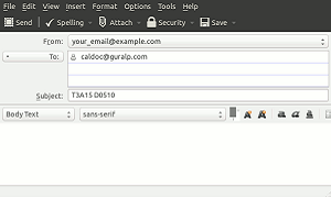
Our server will respond with the calibration details for the sensor and digitiser in Word format. The body of the e-mail will be ignored.
Once you have access to the correct information, proceed to create the InfoBlocks using notepad.exe. To access notepad.exe, key  and type notepad. Press <Enter> and notepad.exe should open with a new, blank document.
Note: Güralp recommend the use of notepad++ which is a free replacement for notepad.exe with significantly enhanced features.
Enter the text of the InfoBlock as in the following example:
Serial-Nos=T5F18
VPC=3.17,3.19,318
G=0.512,0.510,0.508
COILCONST=1,1,1
CALRES=1
TYPE=CMG-5T
RESPONSE=CMG-5_100Hz ACC
GRAVITY=9.81089
Each line is explained in detail below:
Serial-Nos=T5F18
This is the sensor's serial numberVPC=3.17,3.19,318
These are the volts-per-count values taken from the CMG-DM24's Calibration Sheet. The vertical value is given first, followed by the North/South and then the East/West values, separated by commas.G=0.512,0.510,0.508
These are the gain values of the sensor and are taken the from the sensor's Calibration Sheet. The vertical value is given first, followed by the North/South and then the East/West values, separated by commas.COILCONST=1,1,1
These are the coil constants for the three components. For a Güralp 5TD accelerometer, these should all be set to unity,as shown.CALRES=1
This is the value of the calibration resistor, in Ω, as given on the sensor calibration sheet. For a Güralp 5T, use CALRES=1.TYPE=CMG-5T
This is the sensor type.RESPONSE=CMG-5_100Hz ACC
This is used as an index into a lookup-table of the Sensor's theoretical values and consists of two parts, the instrument and response code and the response type (ACC or VEL for acceleration or velocity). The most common values for strong motion work are CMG-5_100HZ and ACC but, if you have an unusual requirement, please see the Scream! manual for a list of all possible values.GRAVITY=9.81089
This should specify the local value for acceleration due to gravity, if known.
Create one file per sensor, save them onto the PC's desktop and then close notepad++ or notepad.
4.2.2 Accessing Scream! and uploading InfoBlocks
The system is preconfigured so that seismicmonitor.exe always appears on top of any other windows, but Scream! will have been started in a hidden window. Access the Scream! window by holding down the  key and then pressing the
  key, possibly repeatedly, until the Scream! icon is highlighted, then release the key.
Scream will display its main window, including, in the left hand “tree” window, a list of all connected data sources. Right-click on the icon for the COM port corresponding to your digitiser and, from the drop-down menu, select terminal.
A new window will open, connected to the digitiser's command line and you should see a command prompt. Enter the command
re-boot
and, when prompted, confirm with  .
.
As part of the boot sequence, a system menu is displayed. If this is ignored, the digitiser will start up normally after a short delay. When you see the system menu, key  to select “View/Upload INFOBLOCK”.
Key when prompted to “UPLOAD INFOBLOCK?”
This will open an X-moden transmitter file selection dialogue window where you can select the appropriate InfoBlock file for transmission. If the digitiser has two connected sensors, upload the InfoBlock for the one connected to the SENSOR A port first.
When the file has completed uploading, the X-modem window will close and you will be returned to the command line session with a prompt asking if you want to upload another InfoBlock.
If you have a second sensor connected to the SENSOR B port on the digitiser, upload its InfoBlock now, in the same way as the previous one - the system will reboot automatically after the upload has completed.. If you only have one sensor connected, respond  to the prompt - the system will reboot at this point and the terminal window will close..
Allow a few minutes for the system to boot and you will be presented with a command prompt.
4.2.3 Configuring Strong Motion mode in a Güralp DM24
After the system re-boots, it is necessary to set the digitiser into Strong Motion Mode. At the prompt, type the command
ok-1
This command gives you access to a number of normally “hidden” commands.
The next command varies, depending on whether you have a three-channel or six-channel digitiser. For a
For a three-channel digitiser, enter the command
7 triggers
For a six-channel digitiser, enter the command
$77 triggers
This sets the DM24 into Low Latency Mode, increasing the data throughput so that calculations can be performed in time to transmit computed strong motion results each second. It operates by reducing the digital filter delay.
Enable the strong motion calculations by entering the command
+simode
At this point, the digitiser will start transmitting strong motion data after it is next rebooted. There are several other commands which affect the strong motion calculations: please see the Güralp Systems Strong Motion User Guide, document MAN-SMO-0001, for more details. This document is available on our web site at http://www.guralp.com/documents/MAN-SMO-0001.pdf
After performing all desired strong motion configuration, enter the command
re-boot
and respond with a when prompted.
Note: To return the instrument to normal mode without low latency and with no strong motion packets being transmitted, perform the following:-
Access the digitiser's command line from using the terminal facility in Scream!, as described in Section 4.2.2. At the command prompt type the following commands
ok-1
0 triggers
-simode
re-boot
and respond with a  when prompted.
If you have made further configuration changes, refer to the Strong Motion User Guide for details of how to reverse them.
Close the terminal window and, after waiting for the instrument to finish booting, check that data streams are arriving in Scream! by ensuring that figures in both the the “End Time” and “RIC” columns are changing regularly. Return to seismicmonitor.exe by holding while using the key.
Note: Do not close Scream! - it must be running in the background.
4.2.4 Strong motion stream IDs
If you are using an EAM, you will, at this point, notice a lot of extra streams appearing. The digitiser issues strong motion data blocks which the Güralp EAM decomposes into twenty-four individual streams. The last two characters of the stream ID are used to designate the type of result being transmitted. The following tables only cover the additional streams resulting from the strong motion data.
The second to last character is decoded as follows:
Character | Meaning |
Z | Vertical axis |
N | North/South axis |
E | East/West axis |
2 | two-dimensional horizontal resultant |
3 | three-dimensional resultant |
The last character will be one of the following:
Character | Meaning |
O | Windowed MMA minimum |
Q | Windowed MMA maximum |
T | Windowed MMA average |
P | Peak Ground Acceleration (PGA) |
R | Root Mean Square (RMS) |
S | Spectral Intensity (SI) |
4.2.5 Setting the time zone
If you wish the time on the display panel to be displayed in your local time instead of UTC, add a line like
TimeZone=-6
to the [setup] section of the sms.ini file. In the example above, time will be displayed in CT, which is UTC minus six hours. The system must be rebooted for this change to take effect.
See Section 4.7 for details about editing the sms.ini file.
4.3 The strong-motion packet import app
4.3.1 The ini file
The strong-motion packet import app is configured by editing a single .ini file, located in the folder C:\Program Files\Guralp Systems\gdi-sm-app
Note: Changes made to this file will affect the running application immediately: there is no need to restart the application after reconfiguration.
The contents of a typical file look like this:
[gdi-rx]
ip=192.168.1.1
port=1565
sysid=GSL-DEMO
[sms-tx]
ip=127.0.0.1
port=1567
[logging]
LogToFile=y
LogFile=C:\Program Files\Guralp Systems\gdi-sm-app\gdisms.log
[system]
DataTimeout=5
CheckTimer=5
StartMinimised=y
The [gdi-rx] section contains the IP address and port number of the source acquisition module, along with the sysid, which is the first past of the channel name. All three values are required and have no defaults.
Note: A DAS. NAM or Affinity will serve GDI data on port 1565 in its default configuration.
The [sms-tx] section contains the IP address and port number to which the strong motion packets will be sent. Both are required and there is no default value for either. The correct values for use with the Güralp Strong Motion display panel are 127.0.0.1 for the IP address and 1567 for the port, as shown in the example.
The [logging] section contains entries to control the application event logging. Facilities are available to log to the Windows event log or to a text file, the name and location of which can be specified. Enable logging with a “y”. Any other character will disable the logging. If the LogFile parameter points to a non-existent file, the application will attempt to create the file as well as any missing parent folders.
The [system] section contains entries to control how often the application performs self-checks. The application periodically checks the following to ensure strong motion packets are being sent and received reliably:
The connection to the acquisition module
Reception of data values
Transmission of data packets
DataTimeout specifies the time used to determine if strong motion values and packets are being received and transmitted properly. The CheckTimer value determines how often to check the connection and data transmission and reception. Both of these time values are in seconds.
If any one of the items is not correct the application will attempt to re-start the link to the acquisition module.
4.3.2 Operation
The application will attempt to connect to the acquisition module specified in the ini file. If a connection cannot be established the application will continue trying. Indication of the connection progress will be shown in the status bar at the bottom of the main form.
Once a connection is made, the application will receive a list of the strong mode data channels and will then start receiving data for those channels. The channels and data are displayed in the grid in the centre of the main form.
If configured to do so, the application may start minimised in the task tray. In order to restore the application simply click on the icon.
There are two button on the form labelled  and
and  . Clicking the button will cause the application to disconnect from the acquisition unit and attempt to connect again. This maybe useful should the application get into a state where data is not being sent to the SMS application, but the application checks have not corrected the condition.
The button will cause the application to be minimised to the task tray: this is the normal operational mode.
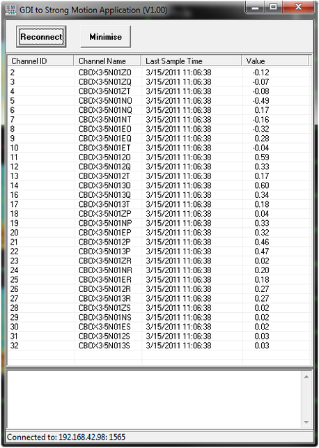
If minimised, the window can be brought back to the foreground by holding the key while repeatedly pressing until it is visible.
4.4 Configuring analogue outputs.
The Strong Motion Display is equipped with four analogue outputs which can be used to pass computed strong motion results to external equipment. Each output is connected to a current driver in series with the output of a DC-DC converter and will provide 4mA of current when there is no in put, rising to 20mA at a configurable full-scale, with 30 volts available to drive external loads.
The “Outputs” tab of the main interface allows the operator to select which strong motion parameters influence each of the four outputs, along with the value corresponding to full-scale (20mA) output.
Select the “Outputs” tab by touching the  button near the bottom of the display screen. The lower part of the display will change to show the following (the grey areas are described later):
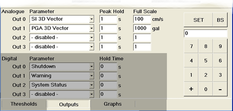
The four analogue outputs, “Out 0”, “Out 1”, “Out 2” and “Out 3” each have a drop-down menu control which allows the operator to select which strong motion result is used to control the output current.
The choices are:
Next to the drop-down menu is a field which allows the operator to control the associated peak hold time. Using this, the outputs can be configured to maintain each peak level for several seconds in order to allow time for external equipment to react. As the incoming data is single sample per second, a value of 1 disables this function (every value is held for one second).
Note: the peak hold switch on the main display area of the screen has no effect on the peak hold associated with the analogue outputs.
To change any of the peak hold values, touch the value you wish to change and then either use the  and
and  buttons on the right-hand side of the panel to increment or decrement the value, or “type” a new value using the touch-keyboard on the right-hand side of the panel and then touch the
  button. Touch the
  button (back-space) to correct any entry errors.
The third column allows the value associated with the maximum current output to be set. The units will be chosen automatically based on the parameter being monitored. Change these values by touching them and then using the touch keyboard as described in the previous paragraph.
4.5 Configuring digital (relay) outputs
The Strong Motion Display contains four relays which can be used to trigger external actions if selectable strong motion results exceed configurable values. These are typically used to provide warning alarms if a lower threshold is exceeded and to automatically shut down vulnerable equipment in monitored structures if a higher threshold is exceeded.
There are four threshold values in all: warning and shut-down for Peak Ground Acceleration (PGA) as well as warning and shut-down for Spectral Intensity (SI). These values are displayed and set from the “Thresholds” tab of the main display, as described in Section 4.5.3.
When any monitored values exceed a configured threshold, an audible alarm is sounded. Different alarm tones are used for warning and shut-down events.
4.5.1 Assigning relays to events
The “Outputs” tab of the main interface allows the operator to select which strong motion parameters influence each of the four relay outputs.
Select the “Outputs” tab by touching the  button near the bottom of the display screen.
The lower part of the display will change to show the following (the grey areas have been described in the previous section):
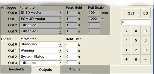
The four digital outputs, “Out 0”, “Out 1”, “Out 2” and “Out 3” each have a drop-down menu control which allows the operator to select which strong motion result is used to control the output relay.
The choices are:
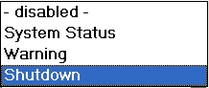
When set to “disabled”, the associated relay will never operate. When set to “Warning” the associated relay will operate when either of the the lower, warning thresholds (as configured in the “Thresholds” tab is exceeded by any of the monitored values. When set to “Shutdown” the associated relay will operate when either of the the higher, shut-down thresholds as configured in the “Thresholds” tab is exceeded by any of the monitored values.
If set to “System Status”, the relay will operate if the unit detects that it is no longer receiving incoming seismic data. This can be used to signify that a fault has occurred elsewhere in the system.
Warning: because the relays are of the normally-open type, the System Status monitoring cannot detect a problem with the CMG-STA itself or, for example, with the power supply to it. The output of a relay configured to respond to System Status events cannot be relied upon as an indication that the system is running correctly and additional steps must be taken in safety-critical applications.
If a threshold is exceeded by a monitored component and a relay is assigned to that event, the relay contacts will remain closed for the duration of the event plus an optional, additional hold time. This time can be configured by using the fields in the “Hold Time” column associated with each output. If the hold time is set to zero, the relay contacts will remain closed until the operator touches the  button on the main display.
To change any of the hold time values, touch the value you wish to change and then either use the and buttons on the right-hand side of the panel to increment or decrement the value, or “type” a new value using the touch-keyboard on the right-hand side of the panel and then touch the button. Touch the button (back-space) to correct any entry errors.
4.5.2 Selecting monitored components
Any component shown in the upper part of the main display can be set to be monitored (for the purposes of the relay outputs) or not by touching the component label. The label for a monitored component is displayed in white on a black background: when unmonitored, this changes to be black on an ivory background.
4.5.3 Setting threshold values
Thresholds can be set independently for Peak Ground Acceleration (PGA) and Spectral Intensity (SI). For each, the lower threshold is referred to as the “Warning” threshold and the higher is referred to as the “Shut-down” threshold.
To set the threshold values, touch the  button at the bottom of the display. The bottom of the display changes to show the following:
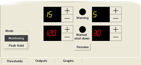
The four threshold levels can be set by touching the increment ( ) and decrement (
 ) buttons next to each value.
If the warning threshold is exceeded by any value in the column above it, the black circle above the word “Warning” will turn amber and remain so until the operator touches the button. Similarly, if the shut-down threshold is exceeded by any value in the column above it, the black circle above the words “Manual shut-down” will turn red and remain so until the operator touches the button.
4.6 Securing the system
The Strong Motion Display provides a simple mechanism to prevent the modification of any subset of its configuration parameters. The values of all configuration parameters are stored in a single configuration file and this file also includes flags associated with each parameter which, if enabled, prevent further modification of the associated value. This mechanism allows a system to be fully configured and then partially or completely “locked down”. The process relies on the use of a PC keyboard, together with an understanding of the mechanism involved. Once the keyboard is removed, it becomes impossible to re-enable any features which have been disabled (except as described in the following paragraph).
It is possible, via the configuration file, to configure an over-ride pass-code. If the pass-code is entered, it is again possible to edit all parameters. This over-ride mode can be turned off with a button on the screen or will turn off automatically after a configurable time of inactivity.
Every time a parameter is changed via the touch-screen interface, a corresponding value is changed in the configuration file, which is immediately written to disk. If the system is re-booted, it loads its initial values from the configuration file. Each parameter in the file has an associated flag to configure whether it is editable or locked. If locked, the relevant on-screen controls are “greyed out” and unavailable to the operator.
The configuration file is organised so that every parameter is described by an informative comment and the default value for the parameter is provided immediately after the comment. Values that have changed from the default are grouped at the end of the file. This organisation is not mandated but it is recommended that the configuration engineer follows the same pattern when making changes.
4.7 The configuration file
The configuration file for seismicmonitor.exe is called sms.ini and is located in C:\Program Files\Guralp Systems\SMS. It can be edited using notepad.exe.
Note: Güralp recommend the use of notepad++ which is a free replacement for notepad.exe with significantly enhanced features.
To access notepad.exe, key and type notepad. Press <Enter> and notepad.exe should open with a new, blank document. Key + to open the file menu, then type
  to access the File Open dialogue. Type C:\Program Files\Guralp Systems\SMS into the “File name” field in order to open the file.
When finished editing, key  +
+ to save the file then +
 to exit notepad.
A typical configuration file contains the following:
[setup]
; Lines in this file starting with a ";" are comment lines,
; to describe the parameter. Lines starting with a "#"
; indicate the defaults if the parameter is not specified.
; It is recommended that if you want to change
; a parameter from the default, you ADD a line in below the
; default to set the new value. Do not remove the default
; line - this is useful as a reference.
; Both lines starting with ; and # are seen by the system
; as comments.
; ActiveChans is a bitmask of the channels to enable.
; bit 0=EW, 1=NS, 2=UD, 3=HV, 4=3D. Default is all bits on.
# activechans=255
; NetPort is the UDP port number to listen for incoming GCF
; packets on.
# NetPort=1567
; System is the "SysID-SerNum" ID to match on for data
; display. If not specified, the program locks onto the
; first one received.
# System=
; Relays can be configured to activate on a given
; parameter. Parameters are encoded as
; 0=not used, 1=Status alert, 2=Warning, 3=Alarm
# Relay0.parameter=3
# Relay1.parameter=2
# Relay2.parameter=1
# Relay3.parameter=0
; When a parameter activates a relay, it can be held
; activated for a specified amount of time after the event
; has finished. A value of 0 leaves the relay on until the
; operator presses "Resume".
# Relay0.HoldTime=0
# Relay1.HoldTime=0
# Relay2.HoldTime=0
# Relay3.HoldTime=0
; The system "status" includes a data watchdog - if no data
; has been received ; for the set number of seconds, the
; "status" line is activated. A value of 0 means the
; function is disabled.
# DataWatchdog=10
; WarnLevel and AlarmLevel specify the warning and alarm
; levels respectively that the system starts up with.
# SIWarnLevel=5
# SIAlarmLevel=30
# PGAWarnLevel=15
# PGAAlarmLevel=120
; WarnWAV and AlarmWAV specify WAV audio files that are
; played when warning and alarm conditions are triggered.
# WarnWAV=sms_warning.wav
# AlarmWAV=sms_alarm.wav
; ClickWAV specifies the clicking sound when an active
; "button" is pressed. If the file is missing, invalid, or
; incorrectly specified, the default system beep will be
; used instead.
# ClickWAV=sms_click.wav
; FlashOnWarn and FlashOnAlarm are flags that enable
; whole-screen flashing : yellow or red for warning and
; alarm conditions respectively.
# FlashOnWarn=0
# FlashOnAlarm=0
; The "parameter" values select which calculated value is
; output to which DAC (ie current loop)
; 1..5 are for SI, 6..10 are for PGA. The order is
; EW,NS,UD,HV,3D
; A value of 0 means disabled, or not used
# DAC0.parameter=5
# DAC1.parameter=10
# DAC2.parameter=0
# DAC3.parameter=0
; The "fullscale" values set the full-scale value that
; produces maximum output on the DAC. Units are of the
; value selected in "parameter" above, for each DAC.
# DAC0.fullscale=100
# DAC1.fullscale=1000
# DAC2.fullscale=1
# DAC3.fullscale=1
; The "window" value specifies that the maximum from the
; last 'n' seconds of samples is output to the DAC. Valid
; range 1-255, 1=current value only.
# DAC0.window=1
# DAC1.window=1
# DAC2.window=1
# DAC3.window=1
; ResumeClearsPeak, if enabled, causes the peak values to
; be cleared when the resume button is clicked. If the Peak
; Hold function is selected, it will re-start building a
; peak value.
# ResumeClearsPeak=1
; PeakHold is a flag that selects if the Peak Hold option
; is on at startup.
; If not, then the panel is in "monitoring" state.
# PeakHold=0
; EditControl is a bitwise set of flags controlling which
; options are editable by the operator. If the option is
; not set, the only way to change the option is to stop the
; program, change this INI file, then re-start the program.
; This function is provided to give an admin the option to
; prevent an operator from changing some critical
; functionality. The default is all editing enabled. The
; following bits control access:
; 0 (1) = Change which channels are monitored
; 1 (2) = Change the warning & alarm thresholds
; 2 (4) = Change the Analogue Out0 options
; 3 (8) = Change the Analogue Out1 options
; 4 (16) = Change the Analogue Out2 options
; 5 (32) = Change the Analogue Out3 options
; 6 (64) = Change the Digital Out0 options
; 7 (128) = Change the Digital Out1 options
; 8 (256) = Change the Digital Out2 options
; 9 (512) = Change the Digital Out3 options
# EditControl=65535
; AdminCode is an optional parameter that sets the CODE
; necessary to enable editing of parameters when the
; EditControl is used to prevent some or all normal access
; to the settings. If EditControl is not specified (ie
; everything editable), this is not used. It can be any
; sequence of digits up to 5 characters.
# AdminCode=12345
; AdminTimeout sets the number of seconds after which the
; admin "mode" times out if no keys are pressed. A value of
; 0 disables timeouts completely.
# AdminTimeout=60
; Graph?Selection (5 entries), where ? is the graph number
; (0-4) selects which parameters are drawn in each graph.
; The values are bit-coded.
; The defaults are: E/W MMA, N/S MMA, Vertial MMA,
; Horizontal MMA, Vertical MMA
# Graph1Selection=7168
# Graph2Selection=224
# Graph3Selection=7
# Graph4Selection=229376
# Graph5Selection=7340032
; LogPath sets the folder to store the log files in.
# LogPath=c:\sms_logs
; LogHistory sets the number of days of log files to keep.
; Note: it only affects the current "LogPath" folder, so if
; you move the LogPath, the old files in the old folder
; will not be touched. A value of 0 disables logging.
# LogHistory=7
activechans=239
SIWarnLevel=5
SIAlarmLevel=30
PGAWarnLevel=15
PGAAlarmLevel=120
relay0.parameter=3
relay1.parameter=2
relay2.parameter=1
relay3.parameter=0
relay0.HoldTime=0
relay1.HoldTime=0
relay2.HoldTime=0
relay3.HoldTime=0
DAC0.fullscale=100
DAC1.fullscale=1000
DAC2.fullscale=1
DAC3.fullscale=1
DAC0.parameter=5
DAC1.parameter=10
DAC2.parameter=0
DAC3.parameter=0
DAC0.window=1
DAC1.window=1
DAC2.window=1
DAC3.window=1
Graph1Selection=256
Graph2Selection=224
Graph3Selection=7
Graph4Selection=229376
Graph5Selection=7340032
PeakHold=0
Note: The configuration file is only read when the main program starts so, after making changes, you should reboot the display panel (by interrupting the power) or restart the seismicmonitor.exe application so that your changes can take effect.
4.8 Customising audible and visible alarms
If a number of Strong Motion Display panels are to be used together in the same room, it becomes useful to change the alarm sounds produced when thresholds are exceeded. Any sound recorded in .wav format can be used - a recorded voice speaking the system ID or location of the monitored sensor can be particularly helpful in large installations.
To make use of this feature, place the desired .wav files in the C:\Program Files\Guralp Systems\SMS directory (they can be transferred to the unit using a USB memory stick) and then edit the configuration file sms.ini as described in section 4.7.
Add the following lines to the end of the file:
WarnWAV=sound_to_use_for_warning.wav
AlarmWAV=sound_to_use_for_alarm.wav
replacing the place-holder filenames above with the names of the files you wish to use.
It is also possible to configure the Strong Motion Display to flash the whole screen to signify a warning or alarm condition (in addition to the audible alerts). The screen flashes in yellow for warnings and in red for alarms. The two conditions can be enabled or disabled independently. To enable these features, add one or both of the following lines to the end of sms.ini:
FlashOnWarn=1
FlashOnAlarm=1
Save the file after editing it and then reboot the Strong Motion Display (by interrupting the power) so that your changes can take effect.
4.9 Viewing strong motion results
4.9.1 The main display
The main display of the Strong Motion Display shows, at the top of the screen, the system ID of the sensor being monitored. If data from several sensors are available to the unit, the System ID box functions as a drop-down menu which can be used to select which system to monitor.
Below the system ID display are shown the data and time as output by the digitiser and, below that, Peak Ground Acceleration (PGA) in Gal (cm/s2) and Spectral Intensity (SI) in cm/s1 are shown for each component.
The PGA and SI values are normally shown in green but, should any values exceed the warning threshold, they are displayed in amber. If any exceed the shut-down threshold, they are displayed in red.
The component labels serve as switches to determine which components are monitored for the purpose of the relay outputs, as described in Section 4.5.2. A monitored component has its label displayed in white on a black background and an unmonitored component is labelled in black on an ivory background.
Below the PGA/SI display is a dialogue which can has three tabs, “Thresholds”, “Outputs” and “Graphs”.
The “Thresholds” tab allows the setting of threshold values as described in Section 4.5.3. In addition, it contains a mode switch which can be set to either “Monitoring” or “Peak Hold”. When set to “Monitoring”, the PGA and SI displays are updated each second as new data arrives. When set to “Peak Hold”, the displays show the highest value encountered so far and are only updated if a higher value is received. The peak values displayed can be reset by switching the unit to “Monitoring” mode and back.
The “Outputs” tab is fully described in Sections 4.4 and 4.5, starting from page 21.
The “Graphs” tab is described in the following section.
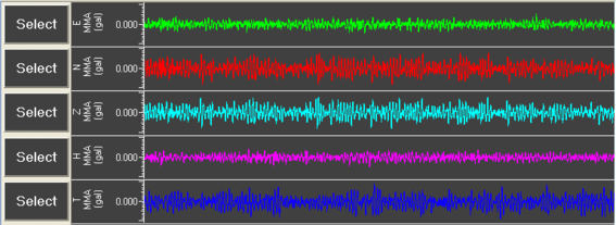
4.9.2 The graphical display
The “Graphs” tab of the main display can display up to five separate graphs, each showing up to five components. Each graph can display Peak Ground Acceleration (PGA), Spectral Intensity (SI) or Maximum/Minimum/Average (MMA) data for the selected components. If fewer than five graphs are required, the available screen-space can be divided between the chosen number of graphs as desired.
To the left of the graph area are five select buttons,  , which can be used to select the data sources for each graph. If no data source is configured on a given button, the graph above expands downwards to occupy 20% more of the available space and the resolution of the expanded graph is adjusted accordingly.
For example:
To have just one graph occupying all of the available space, select the desired parameter (PGA, SI or MMA) and components using the top
button and make sure that no components are selected on the remaining buttons - they will be displayed as black text on an ivory background to show that they are unconfigured, while configured buttons are displayed in white on black:  .
.To have three graphs, with the middle one occupying 60% of the available space and the top and bottom ones occupying 20% each, select data sources using the first, second and last “Select” buttons, leaving the third and fourth unconfigured.
To select data sources for a graph, touch the appropriate button. A dialogue will glide into view:

Use the top three buttons to choose between MMA, PGA and SI and then, for the chosen measurement, select up to five components to display. If you select none, the adjacent area will be allocated to another graph. If you change between MMA, PGA and SI and make fresh component choices, any component settings on the previous tab will be lost. Touch the  button when you are finished.