Chapter 3. Configuration procedure
3.1 The configuration interface
The Lantronix modules provide a web-based configuration interface on port 80 which is normally the preferred method of configuration. A character-based configuration menu is also provided. This is accessible either (i) by using telnet to connect to port 9999 or (ii) by using a terminal emulator to connect to either of the serial ports and interrupting the boot process. When integrated into a Güralp CD24, only the first serial port (Channel one) is available for this purpose.
If the networking is malfunctioning or misconfigured, access via the serial port is sometimes the only method of reconfiguring the module. The rest of this document assumes that this is the method being used.
A terminal emulator is provided within Güralp Systems Ltd.'s Scream! software but, if this is not available, minicom (for Linux) and PuTTY (for Windows) are both freely downloadable, tested alternatives. Many other terminal emulators are available: this document assumes that the user is familiar with their chosen emulation software.
3.1.1 Cabling
On Güralp CD24 digitisers and Güralp 6TD instruments, Channel 1 of the Lantronix module is exposed on pins N (TxD), P (RxD) and L (ground). Power (10 to 36V DC) needs to be supplied via pins A (+ve) and B (0V). A special 'Y' cable, CAB-PEP-0041, is available from Güralp Systems Ltd. for providing both of these connections or the user may choose to make their own, according to the specification in Section 4 on page 12.
3.1.2 Emulator settings
The terminal emulator should be configured for:
9600 baud
8 data bits
one stop bit
no parity bit
no hardware flow-control
no software flow-control
3.1.3 Connecting
With the power supply turned off, connect the cable between the digitiser and the power supply, then connect to the PC running the terminal emulator. Start the emulator and configure it as in the preceding section.
Hold down the  key and, while keeping it held down, turn on the power supply to the digitiser. After a delay (which may be as long as one minute), the MAC address will be displayed. Key
  and the Lantronix module will display a set-up menu, as shown below (details may vary):
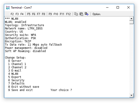
It is normally advisable to reset the unit to its factory defaults by selecting option  from this menu.
3.1.4 Using the menu
Throughout the configuration interface, the user is prompted for a series of configuration settings in turn. The current value is always offered as a default and this can always be selected by pressing the key. After all the settings for any given section are configured, the user is returned to the top-level menu, as shown above.
3.2 Configuring serial channel 1
Serial channel one is not normally used and menu option  from the top-level menu can be ignored. Please contact Güralp Systems Ltd. technical support if you wish to use this port for supporting an external serial device and would like help configuring it.
3.3 Configuring serial channel 2
Serial channel two is connected internally to the CD24's data output port and is used for all seismic data and digitiser configuration when the operator is connected via a network.
The factory defaults for the serial settings for channel two do not provide the most efficient Ethernet utilisation and should be changed; the FlushMode should be set to F7 - two characters - as shown below. If a non-standard baud rate is desired, it should also be configured at this point. (The same baud rate must then be configured in the CD24 by using the BAUD command from the digitiser's command line: see the CD24 manual for more details.)
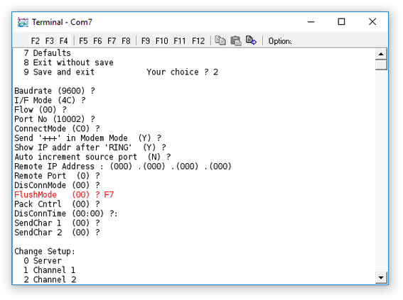
To be sure of the correct configuration, first select option from the top-level menu to restore factory default settings. Next, select option  from the top-level menu and, if necessary, enter the chosen baud rate at the first prompt; key at the next prompts, retaining the default settings, until prompted for FlushMode.
Key  then at this prompt and then key at the remaining prompts.
3.4 Configuring the wired network interface
To configure the wired network (Ethernet) interface, select option  from the top-level menu. You will be prompted for the network mode: select for wired only.
You will next be prompted for the IP address, as four separate values. If you wish to use DHCP, enter for each of these values; if not, enter the desired static IP address.
If your network uses a router, enter  at the “Set Gateway IP Address” prompt: you will be prompted to enter details of your network's default router. If you do not use a router or do not wish to route packets from the CD24, enter
  at this prompt.
The following two questions allow you to configure a netmask and a DNS server, if you wish. Entering at the netmask prompt will result in the default netmask being signed. This is based on the IP address according to the traditional “classful” addressing scheme.
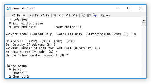
In the example above, a default netmask of 255.255.255.0 will have been assigned because addresses beginning 192 are in class C.
3.5 Configuring the wireless network interface
Where the end-user has not requested pre-configured wireless networking, systems are shipped with the default SSID LTRX_IBSS and with wireless security disabled. You can, of course, configure any desired configuration at this point.
To configure wireless networking, take option from the top-level menu and then enter at the first prompt to select “Wireless Only” mode. Complete the remaining system configuration questions as described in the previous section.
Next, select option  for WLAN configuration.
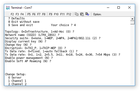
The following section describes a standard infrastructure WLAN configuration with WPA+TKIP security but you should enter values applicable to your own application:
Topology : enter
= InfrastructureNetwork Name (SSID) : Type the desired SSID
Security Suite : enter
= WPADisplay current Key :
(a Yes or No option)Change Key :
(a Yes or No option)Key Type Choose: enter
Enter Key : type the desired key value
Encryption: enter
= TKIP (or as required)TX Data Rate: enter
= Auto FallbackTX Data Rate: enter
 = 11 (Mb per second)
Enable Power Management:
(a Yes or No option)Enable Soft AP Roaming:
(a Yes or No option)
3.6 Saving your settings
Once all desired configuration changes have been made, enter  at the top-level menu in order to 'save and exit'.