Chapter 3. First encounters
3.1 Unpacking and packing
The 5TB seismometer is delivered in a single transportation case, which is specifically designed for the 5TB. This packaging should be reused whenever you need to transport the sensor. Please note any damage to the packaging when you receive the equipment, and unpack on a clean surface. The package should contain:
the seismometer;
a cable to join the sensors to the surface control box;
the surface control box;
the hole lock control unit, if ordered;
a cable strain relief mechanism, if ordered;
a Hand-held Control Unit (HCU) for monitoring sensor outputs and calibration, if ordered;
an inclinometer monitor box;
a calibration data sheet;
this manual.
3.2 Handling notes
The 5TB is a sensitive instrument, and can be damaged if mishandled. It will not stand vertically upwards without support, and should not be operated until it has been securely installed in a borehole casing. If you are at all unsure about the handling or installation of the device, you should contact Güralp Systems for assistance.
Avoid bumping or jolting any part of the sensor when handling or unpacking.
Keep the sonde sections vertical wherever possible. Carry them by hand and store in a safe rack. Never drag or roll the sonde. If the sensor system topples over, you must inform Güralp Systems.
Keep all the parts of the sensor system protected and clean so that they can be joined together securely. Store in the original packaging if possible.
Do not kink or walk on the data cable (especially on rough surfaces such as gravel), nor allow it to bear the weight of the sensor.
Do not connect the instrument to power sources except where instructed.
The 5TB is delivered as a single package, with its sections (including hole lock and magnetometer units, if ordered) already joined together. You should not need to disassemble it.
3.3 Control units
Once it has been installed, the 5TB is operated from the surface through various control units. All the 5TB's functions can be accessed through one or other unit. Most can be removed from the site once the instrument is ready for use.
Some of these control units are optional and may not have been supplied with your installation. Their functions can be duplicated either by applying voltages directly to control lines (see appendixes for pin-out information) or through a connected Güralp digitizer such as the DM24. The DM24 digitizer is able to pass commands to the instrument from an Enhanced Acquisition Module (EAM) or a computer running Güralp Systems' Scream! software, allowing you to access all of the instrument's functions remotely.
3.3.1 The surface control unit
This box should be installed in a surface enclosure, if you are not connecting the 5TB directly to a digitizer. It provides connections for the various elements of the sensor system.
If you are using a down-hole DM24 digitizer, it will be supplied with its own surface control unit, which differs from the one described here. See the DM24 operator's guide for more details.
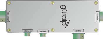
The SENSOR connector is a 32-way military specification bayonet plug, and should be connected to the borehole instrument.
The RECORDER connector is a 26-way military specification bayonet plug. This should be connected to an analogue data recorder or stand-alone digitizer. In systems using down-hole digitizers, this is replaced by a 10-way military specification bayonet serial connector for attaching to a Enhanced Acquisition Module (EAM), modem or other communications link.
The CONTROL or HCU connector is a 26-way military specification bayonet plug intended for connecting to an external controller or Hand-held Control Unit, with the same pin out as the RECORDER connector.
The POWER/HOLELOCK connector is a 10-way military specification bayonet plug, which should be connected to a source of 12 – 30 V DC power, for supplying to the borehole instrumentation.
This connector also provides pins for the hole lock mechanism. To manipulate the hole lock, you should connect it to a Hole-lock Control Unit. Because of the high voltages employed, the hole lock circuitry is entirely isolated from the rest of the electrical systems in the sensor and surface unit; it is not usual to power the sensor whilst using the hole lock.
The COMPASS connector is 6-way military specification bayonet plug giving access to the optional electronic compass's signal and power lines. These are separate from the main instrument so that the compass and sensor can be operated separately. You may need to make up a suitable cable to operate the compass. See section 3.5 on page 14 and chapter 7 on page 42 for more details.
The borehole control unit is supplied with a 3 metre cable as standard. This can be extended up to 100 metres without compromising signal quality. The sensor uses amplifiers with high common mode rejection to ensure the signal to noise ratio is maintained over this distance. Individually shielded twisted-pair cabling must be used for the sensor outputs, control lines and power supply. If you need to make up a suitable cable, you should confirm the cable type with Güralp Systems.
3.3.2 The hand-held control unit
This portable control unit provides easy access to the seismometer's control commands, as well as displaying the output velocity and mass position (i.e. acceleration) on an analogue meter.
This HCU is based on that used for the Güralp 40T, so some of the markings are not relevant to the 5TB.
3.3.2.1 Connections
The HCU provides
two identical 26-pin connectors for attaching to the HCU or RECORDER connectors of the Surface Control Unit, and
a 10-pin connector through which you can power the instrument, if desired. The power pins on this connector are directly connected to those on the sensor and POWER/HOLELOCK connectors of the Surface Control Unit. When using this alternative power connection, you should ensure you do not inadvertently connect two power supplies together.
3.3.2.2 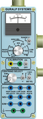 Signal meter
The upper section of the HCU contains a simple voltmeter for monitoring various signals from the instrument.
To monitor the low-gain acceleration outputs, switch the dial to V, N/S or E/W LOW VEL according to the component you want to monitor. Also use these settings to monitor the mass positions.
To monitor the high-gain acceleration outputs, switch the dial to V, N/S or E/W HIGH VEL.
The V, N/S or E/W MASS POS settings are not connected. To monitor the mass positions, you should use the V, N/S or E/W LOW VEL settings instead.
You can set the range of the meter with the RANGE switch. When switched to 10 V, the meter ranges from –10 to +10 V (as marked.) When switched to 1 V, the range is –1 to +1 V.
3.3.2.3 Calibration and control
You can calibrate a 5TB sensor through the HCU by connecting a signal generator across the yellow and green CALIBRATION SIGNAL inputs and setting the adjacent switch to ON. The sensor's response can now be monitored or recorded, and calibration calculations carried out.
The section of the HCU below the calibration lines controls the motors which adjust DC offsets within the instrument. You can use this section to trim DC offsets within the 5TB: see section 3.4 on page 13 for details.
3.3.2.4 Banana plugs
The remainder of the HCU provides useful connections for each of the signal lines from the instrument, for attaching to your own equipment as necessary.
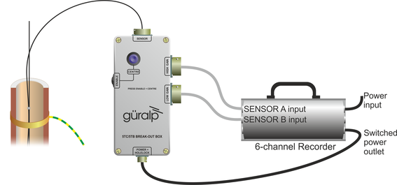
3.3.3 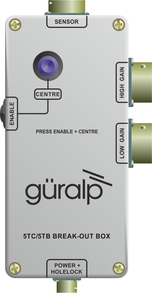 The High-gain/low-gain break-out box
This box separates the high-gain and low-gain outputs of the instrument and routes them to two separate recorder connections, so that both outputs can be digitised at once, allowing the operator to take advantage of the full dynamic range of the instrument.
The six pins which carry the main differential outputs on the high-gain connector are coupled to the high-gain outputs from the instrument. The same six pins on the low-gain connector are coupled to the low-gain outputs from the instrument. With the exception of the power input lines, the other signals are connected as normal so that either recorder connection can be used alone. The power input lines are not connected, so as to avoid accidentally connecting the power outputs of two digitisers together, as described below.
You can connect two separate digitisers as shown:
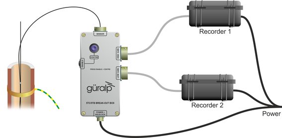
Note: Many digitisers have power outputs so that they can power sensors directly. To avoid shorting together the power outputs of the two digitisers, with consequent risk of damage or even fire, the relevant power input pins on the break-out box recorder connectors are not wired internally. Power for the instrument must be provided through the separate power input connector on the break-out box.
If you have a six-channel digitiser with a switched/monitored power output, such as a Güralp DM24S6EAM or Güralp Affinity, you can connect both of the instrument's outputs simultaneously and use the switched outlet for the instrument, as shown:
3.4 Adjusting DC offsets
Although the 5TB masses do not require centring, you may find that a component outputs a constant DC signal. Inside the 5TB, three motors drive potentiometers which can be used to zero these offsets. The offset circuitry is designed so that each component keeps its full dynamic range whatever the position of the potentiometer.
The easiest way to zero DC offsets is through the Hand-held Control Unit:
Select the component you want to zero from the CENTRING SELECT dial.
Switch the top dial to one of the LOW VEL settings, and set the RANGE to 1 V.
Switch the centring switch to 1 SEC VEL to enable the motor lines.
Press the +/– switch towards – to zero a component from a positive value, or towards + to zero it from a negative value. The adjustment is quite slow, so be careful not to overshoot zero by pressing the switch for too long.
The DC offset is adequately nulled when the low-gain velocity output is within 5 mV of zero. Finer zeroing can be done within Scream! or your recording system.
If you prefer, you can zero the offsets manually. The X, Y and Z Motor lines from the sensor's output, together with the Motor Return line, are brought out on the HCU and RECORDER connectors of the sensor control unit. To operate a motor, apply 4 V between the X, Y or Z line and the Return line. Reverse the polarity to make the motor turn in the opposite direction. If you do not have a source of 4 V, you can use a 12 V source in series with a 47 Ω resistor.
3.5 Operating the hole lock
The hole lock, if fitted, can be extended and retracted using the hole lock control unit:
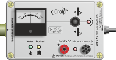
Warning: The hole lock may be using high-voltage mains (outlet) power. Observe suitable precautions.
Connect the hole lock control unit to the HOLELOCK POWER connector of the surface control unit, and to a mains power supply. Alternatively, connect a DC power supply (12 – 24 V) to the input terminals of the hole lock control unit.
Warning: Do not connect both DC and mains power at the same time.
The hole lock control unit supplied in regions with 220 V AC mains (outlet) power differs from that supplied for 110 V AC mains power. You should ensure that you provide the correct voltage to the hole lock control unit, otherwise damage may result to the sensor.
If you are supplying power to the sensor through another connector, ensure that it is switched off whilst you operate the hole lock.
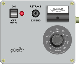
If you are using a deep-borehole hole lock control unit, set the dial to zero.
3.5.1 Engaging the hole lock
To extend the jaw of the hole lock:
Hold the switch on the hole lock control unit in the EXTEND JAW or + position. If you are using a deep-borehole control unit, turn the dial until the built-in ammeter reads around 0.1 A.
When the arm makes contact with the borehole casing, the current will drop slightly. Continue holding the switch in the EXTEND JAW position.
When the lock arm reaches its fully extended position, the motor will automatically stop and the current will drop to 0 A. If using a deep-borehole unit, return the dial to zero.
If the current has not dropped quite to zero after 30 – 40 seconds of operation, release the switch, wait a few seconds, and push it back to the EXTEND JAW position briefly. If the arm is not completely extended, you will see a surge of current. If the current remains constant, the jaw is at its maximum reach.
Once the sensor is locked in place, it is recommended that you remove the hole lock power cable and control unit from the site. Without power, the hole lock will not be able to retract, and the sensor will be secure.
3.5.2 Disengaging the hole lock
To retract the jaw of the hole lock:
Tension the load bearing cable, to take up any slack.
Hold the switch on the hole lock control unit in the RETRACT JAW position or, on a deep-borehole unit, turn the dial until the built-in ammeter indicates 0.3 – 0.5 A. More current is drawn retracting the arm, because the motor is now working against the spring.
When the lock arm reaches its fully retracted position, the motors will automatically stop and the current will drop to 0 A. If using a deep-borehole unit, return the dial to zero.
3.5.3 Manual operation
If you prefer, you can operate the hole lock by applying voltages directly:
To extend the jaw, connect the Hole Lock Motor pin on the sensor (or on the Surface Control Unit's HCU or RECORDER connectors) to a +12 V DC power source, and the Hole Lock Motor Return pin to 0 V.
To retract the jaw, reverse the polarity so that the Hole Lock Motor Return pin is at +12 V DC and the Hole Lock Motor pin is at 0 V.