Chapter 2. Assembling the instrument
2.1 Unpacking and packing
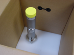
The 40TB seismometer is delivered in a single transportation case, with the sensor system and hole lock mechanism (if ordered) packed separately. The packaging is specifically designed for the 40TB and should be reused whenever you need to transport the sensor. Please note any damage to the packaging when you receive the equipment, and unpack on a clean surface.
The package should contain:
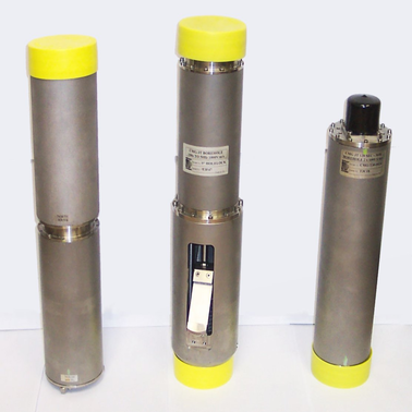
the seismometer, in sections;
a cable to join the sensor to the breakout box;
the breakout box;
the hole lock control unit;
a cable strain relief mechanism;
a Handheld Control Unit (HCU) for monitoring sensor outputs and calibration, if ordered;
a calibration data sheet;
this manual.
The sensor is securely packed, and you will need to remove most of the foam packing before it can be removed.

2.2 Handling notes
The 40TB is a sensitive instrument, and is easily damaged if mishandled. It will not stand vertically upwards without support, and should not be operated until it has been securely installed in a borehole casing. If you are at all unsure about the handling or installation of the device, you should contact Güralp Systems for assistance.
Do not bump or jolt any part of the sensor when handling or unpacking.
Keep the sonde sections vertical wherever possible. Carry them by hand and store in a safe rack. Never drag or roll the sonde.
When the sensor is vertical, keep it securely tied down. If the sensor system topples over, you must inform Güralp Systems.
Keep all the parts of the sensor system protected and clean so that they can be joined together securely. Store in the original packaging if possible.
Do not kink or walk on the data cable (especially on rough surfaces such as gravel), nor allow it to bear the weight of the sensor.
Do not connect the instrument to power sources except where instructed.
2.3 Assembling the 40TB
The 40TB is delivered in separate sections, which need to be assembled before the instrument can be installed in a borehole. It is recommended that you perform these steps with the help of at least one other person.
Important: Make sure your environment is clean and dust free before assembling the unit. Stray fibres or particles cause damage to the “O”-ring seals between the components and may render the sensor unusable. Do not remove the protective caps on the ends of each unit until you are ready.
Ensure that the “O”-ring seals on the hole lock and sensor sections are clean and well greased.
Stand the horizontal sensor on the ground with the packing cap at the top, and support it to prevent it from falling over. This can be done either by using an assistant to hold the casing steady, or by strapping it to a support such as a bench leg.
Remove the packing caps from the top of the horizontal sensor and the bottom of the hole lock unit. Beneath the caps are connectors for the horizontal components.
Hold the hole lock unit above the horizontal sensor and join the connectors. Ensure that each is connected to its correct counterpart. The wires are fairly short, so you will need a second person to hold the instrument whilst you connect them. Take care not to scratch the other components when attaching the connectors.
Align the hole lock unit with the NORTH mark on the horizontal sensor housing. Doing this will allow you to check the approximate orientation of the sensors at a glance.
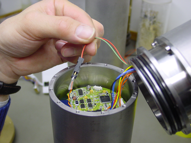
The horizontal sensor consists of two distinct units (the north/south and east/west components), which are supplied already joined together with M3 × 8 cap screws. You should not need to undo this connection.
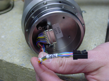
If you do separate the north/south and east/west components, make sure that both the signal cable and, if present, the pass-through to the key switch (red and green, held in the photograph below) are reconnected when you reassemble the instrument.
Push the hole lock unit into the horizontal sensor housing, twisting to align the holes.
Fit twelve M3×8 cap screws into the holes in the joint flange.
When all twelve screws are fitted, begin to tighten them with a ball-ended Allen screwdriver. Tighten evenly, working round the instrument in several passes, until the two sections are securely joined together.
The vertical sensor now needs to be attached to the other end of the hole lock. Remove the packing caps from the top of the hole lock–actuator section and the vertical sensor.
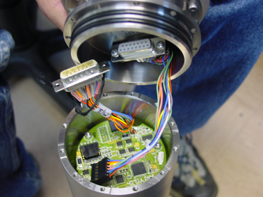
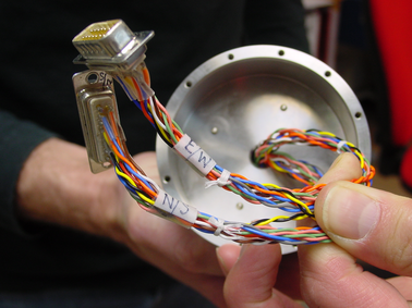
Hold the vertical sensor above the hole lock–actuator section and connect the two 15-way “D”-type connectors, as before. Ensure that each is connected to its correct counterpart.
Push the vertical sensor housing into the hole lock–actuator section, twisting to align the holes.
Fit twelve M3×8 screws into the holes and tighten.
If you are using a single-jaw hole lock unit, attach skids or studs to the sonde as appropriate for your installation, using the fastenings provided.
2.4 Disassembling the instrument
When the instrument is recovered, you may want to disassemble it. To do this, reverse the steps above, bearing in mind the following points:
Make sure you only undo the screws that are necessary to disassemble the instrument, and not the ones which hold each module together. Each joint has several sets of screws holding it together. Only one set from each joint needs to be undone—the set which was added during assembly. For the joint between the vertical sensor and the hole lock, this is the middle set of screws; for that between the hole lock and the horizontal sensors, it is the lower set. The joint between the two horizontal sensors should not be dismantled.
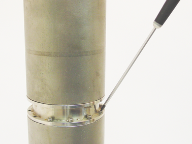
When you detach one module from the next, do not yank them apart, since doing this will damage the connectors inside. Insert flat-head screwdrivers either side of the seal, and carefully lever both sides up simultaneously so that the modules remain parallel. You will need someone to support the upper module as you do this.
When the two parts are separated, tilt the upper one to gain access to the connectors, and disconnect them without scratching the other components.
2.5 Control units
The 40TB is operated from the surface through various control units. All the 40TB's functions can be accessed through one or other unit. Most can be removed from the site once the instrument is ready for use.
Some of these control units are optional and may not have been supplied with your installation. Their functions can be duplicated either by applying voltages directly to control lines (see appendixes for pinout information) or through a connected Güralp digitizer such as the CMG-DM24. The DM24 digitizer is able to pass commands to the instrument from a Data Communications Module (DCM) or a computer running Güralp Systems' Scream! software, allowing you to access all of the instrument's functions remotely.
The breakout box is normally placed where the signal cable emerges from the borehole. It provides connectors for attaching the various other control units, supplies power to the instrument and relays output signals to a recorder or digitizer.
The SENSOR connector is a 32-way mil-spec plug, and should be connected to the borehole instrument with the cable provided.
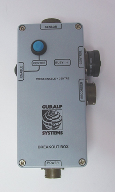
The RECORDER connector is a 26-way mil-spec plug. This should be connected to an analogue data recorder or stand-alone digitizer. In systems using downhole digitizers, this is replaced by a 10-way mil-spec serial connector for attaching to a Data Communications Module (DCM), modem or other communications link.
The CONTROL connector is a 26-way mil-spec plug intended for connecting to an external controller or Handheld Control Unit. It has the same pin out as the RECORDER connector.
The POWER connector is a 10-way mil-spec plug, which should be connected to a source of 12 – 30 V DC power, for supplying to the borehole instrumentation. When operating the hole lock, you should connect the Holelock Control Unit to this connector. Because of the high voltages employed, the hole lock circuitry is entirely isolated from the rest of the electrical systems in the sensor and surface unit; it is not usual to power the sensor whilst using the hole lock.
To calibrate the instrument, the Calibration enable line must be activated. This operates a relay which allows a calibration signal to flow through the transducer feedback coil. This provides an extra force acting on the sensor masses, producing a corresponding deflection in the output signal, which can be analysed by a control computer to extract the seismometer's response characteristics.
Most Güralp instruments are manufactured with active-low Calibration enable lines. However, instruments with active-high calibration can be manufactured on request.
This portable control unit provides easy access to the seismometer's control commands, as well as displaying the output velocity and mass position (i.e. acceleration) on an analogue meter.
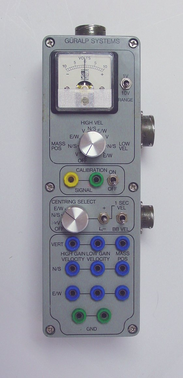
The upper section of the HCU contains a simple voltmeter for monitoring various signals from the instrument.
To monitor the signal outputs, switch the dial to V, N/S or E/W LOW VEL according to the component you want to monitor.
To monitor the mass position outputs, switch the dial to V, N/S or E/W MASS POS. Whilst you are adjusting mass position offsets, you should also switch the instrument out of broadband mode by switching the rightmost CENTRING SELECT switch to 1 SEC VEL, or by holding down the CENTRE button on the breakout box.
You can set the range of the meter with the RANGE switch. When switched to 10 V, the meter ranges from –10 to + 10 V (as marked.) When switched to 1 V, the range is –1 to +1 V.
You can calibrate a 40T sensor through the HCU by connecting a signal generator across the yellow and green CALIBRATION SIGNAL inputs and setting the adjacent switch to ON. The sensor's response can now be monitored or recorded, and calibration calculations carried out. See Chapter 4, page 22, for full details.
Remote null option
If you have ordered a 40T with the remote null facility, you can zero its mass position offsets from the HCU.
Select the component you want to centre from the CENTRING SELECT dial.
Switch the signal meter dial to one of the MASS POS settings.
Switch the rightmost switch to 1 SEC VEL to enable the centring lines.
Press the +/– switch towards – to centre a mass from a positive value, or towards + to centre it from a negative value.
The remainder of the HCU provides connections for each of the signal lines from the instrument, for attaching to your own equipment as necessary.
The borehole sensor system can operate successfully in boreholes with a tilt angle up to 3.5 °. To check that the instrument is installed suitably close to the vertical, a two-axis inclinometer is installed within the sensor housing. The inclinometer monitor unit is used as a visual guide to the sensor's tilt only, and should not be used if precise attitude information is required.
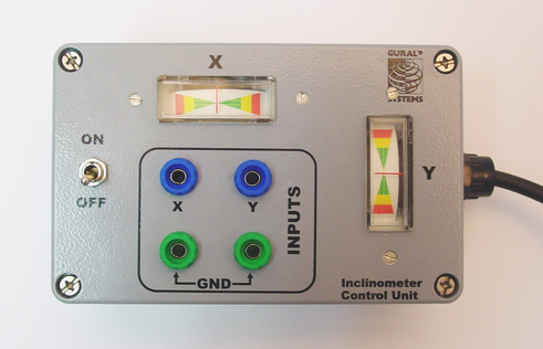
To measure the attitude of a 40TB instrument:
Connect the inclinometer monitor unit to the CONTROL connector of the breakout box.
Switch the ON/OFF switch on the monitor unit to the ON position. The inclinometer is powered separately from other parts of the system; this switch provides power to the downhole circuitry as well as to the monitor unit. The inclinometer should not normally be powered up whilst the sensor is in use.
Read off the X and Y components of the tilt from the analogue meters.
If both tilts are within the green shaded region, the instrument is close enough to vertical that it can be levelled and centred successfully. If either output is in the red shaded region, you should not attempt to centre the sensor masses. Instead, if possible, you should move the instrument within the borehole to a place where it can lie closer to vertical.
If you need to use the outputs of the inclinometer for some other purpose, you can also connect a multimeter to the banana sockets on the inclinometer monitor unit.
2.6 Operating the hole lock
The hole lock, if fitted, can be extended and retracted using the hole lock control unit:
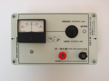
Caution: The hole lock may be using high-voltage mains (outlet) power.
Connect the hole lock control unit to the HOLELOCK POWER connector of the breakout box, and to a mains power supply. Alternatively, connect a 12 – 24 V DC power supply across the input terminals of the hole lock control unit. Do not connect both DC and mains power at the same time.
The hole lock control unit supplied in regions with 220 V AC mains power differs from that supplied for 110 V AC mains power. You should ensure that you provide the correct voltage to the hole lock control unit, otherwise damage may result to the sensor.
Power down the sensor. The hole lock will only function whilst the power is off, to avoid injecting current transients from the mains power supply into the sensor electronics.
If you are using a deep-borehole hole lock control unit, set the dial to zero.

To extend the jaw of the hole lock:
Hold the switch on the hole lock control unit in the EXTEND JAW or + position. If you are using a deep-borehole control unit, there will be an additional dial compared to the unit pictured; turn this until the built-in ammeter reads around 0.1 A.
When the arm makes contact with the borehole casing, the current will drop slightly. Continue holding the switch in the EXTEND JAW position.
When the lock arm reaches its fully extended position, the motor will automatically stop and the current will drop to 0 A. If using a deep-borehole unit, return the dial to zero.
If the current has not dropped quite to zero after 30 – 40 s of operation, release the switch, wait a few seconds, and push it back to the EXTEND JAW position briefly. If the arm is not completely extended, you will see a surge of current. If the current remains constant, the jaw is at its maximum reach.
Once the sensor is locked in place, it is recommended that you remove the hole lock power cable and control unit from the site. Without power, the hole lock will not be able to retract, and the sensor will be secure.
To retract the jaw of the hole lock:
Tension the load bearing cable, to take up any slack.
Hold the switch on the hole lock control unit in the RETRACT JAW or – position. If using a deep-borehole control unit, also turn the dial until the built-in ammeter indicates 0.3 – 0.5 A. More current is drawn retracting the arm, because the motor is now working against the spring.
When the lock arm reaches its fully retracted position, the motors will automatically stop and the current will drop to 0 A. If using a deep-borehole unit, return the dial to zero.
If you prefer, you can operate the hole lock by applying voltages directly to the sensor.
To extend the jaw, connect the Hole Lock Motor pin on the sensor (or on the breakout box's HCU or RECORDER connectors) to a +12 V power source, and the Hole Lock Motor Return pin to 0 V.
To retract the jaw, reverse the polarity so that the Hole Lock Motor Return pin is at +12 V and the Hole Lock Motor pin is at 0 V.