Chapter 4. Installing the 40TB in a borehole
Before installing any instrument in a borehole, it is recommended that you prepare the installation site so there is clear access all around the hole.
Keep the borehole capped at all times except when inserting or removing the instrument, so that debris and tools do not accidentally fall in.
Lay out the cables beside the borehole, or set up a cable drum nearby, so that they do not become tangled.
Ensure the tripod is tall enough to hang the entire installation (sensor and strain relief unit or digitizer) from it, with the sensor off the ground.
Use a winch with a depth gauge if possible, or measure out the cable beforehand.
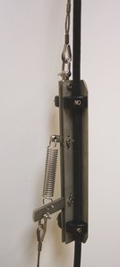
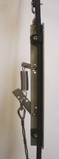
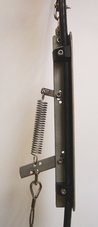
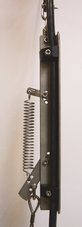
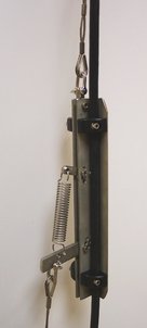
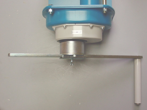
Most installations are equipped with a strain relief unit, which consists of a metal arm that swings out from the load-bearing cable to wedge against the side of the borehole. This removes any strain in the load-bearing cable and prevents vibrations from the surface from being transmitted to the instrument. In installations with a down-hole digitizer, the strain relief arm is fitted to the base of the digitizer sonde; the phrase “strain relief unit” in the following instructions should be taken to refer to the digitizer's strain relief arm.
4.1 Installing a sensor with hole-lock unit
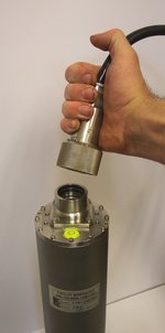
Connect the signal cable to the connector on top of the sensor. Ensure that the “O”-rings inside the housing are clean, and tighten the knurled connector nut to its end stop.
If applicable, you should test the hole-lock mechanism before installing the sensor. For safety reasons, the hole-lock is normally supplied with the arm extended.
To test the mechanism, connect the signal cable to a breakout box and Hole-lock Control Unit, and attempt to retract the hole-lock arm (see Section 3.6, page 17.) If this fails, you should contact Güralp Systems. Extend the arm once more.
Fix the main lifting cable to the shackle on top of the strain relief mechanism, and run the signal cable through the mechanism using the built-in clamps (without tightening them.) Do not allow the signal cable to bear any of the sensor's weight.
Attach the lifting loop to the sensor using four M5×16 screws (provided).
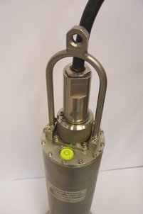
Join the loop to the bottom of the strain relief mechanism using the linking cable provided.
Using a small winch, hoist up the sensor package and strain relief mechanism until both are hanging by the lifting cable, with the strain relief mechanism extended. Tighten the cable clamps on the strain relief unit, allowing a little slack in the signal cable.
Fix the signal cable to the main lifting cable about one metre above the strain relief mechanism using a metal clamp (a nylon cable tie may be sufficient for shallow installations.) Leave a little slack in the signal cable between the clamp and the strain relief mechanism.
Position the assembly over the top of the borehole. Do not allow it to drag across the ground.
Lower the sonde so that its base is just level with the borehole mouth. If there is a depth gauge on the winch, set this to zero.
Continue to lower the sonde to a depth of about one metre, so that the instrument is still visible.
Extend the hole-lock arm (see Section 3.6, page 17) to check that it fits your borehole. The current drawn should dip slightly as the arm touches the casing, then drop to zero when it is fully extended. Check that the sonde is firmly anchored to the borehole casing by attempting to slacken the load bearing cable. If it remains taut, the sonde is still loose within the borehole. Do not proceed with installation in this case. Instead, you should either move the instrument to a narrower section of the borehole and try again, or contact Güralp Systems to fit a longer hole-lock, quoting accurate measurements of your borehole.
Power up the instrument from a suitable power supply.
Level and centre the sensor (see Section 4.5, page 38) so that it can be tested.
Check that the sensor is functioning correctly by connecting a meter or monitoring device to the sensor outputs. If the sensor fails to register ground movements, contact Güralp Systems.
Gently lower the sensor to the required depth. At approximately 20 metre intervals, fix the signal cable to the load bearing cable using metal clamps (nylon cable ties every five metres may be sufficient for shallow installations). This will ensure that the signal cable does not become kinked or trapped within the borehole. Leave a little slack on the signal cable each time, so that it does not bear any weight. Too much slack, however, will cause the cable to scrape against the borehole casing.
Fix the sensor system into the borehole using the hole-lock arm (see section 3.6, page 17.)
If you are installing a 40TB in a deep borehole, the weight of the sensor will stretch the load bearing cable slightly. Remember to allow for this when raising or lowering the cable in the following steps.
Use the winch to drag the assembly up within the borehole for a distance of 15 – 30 cm. This will ensure that the hole-lock arm and the skids or studs on the sonde keep the sensor package vertical within the borehole. Do not drag too far, or you will damage the contact points.
Lower the load bearing cable by around 30 cm to engage the strain relief unit inside the borehole casing, and to provide some slack in the cables.
Clamp the load bearing cable to the top of the borehole.
Tie the lifting and signal cables together above the strain relief mechanism using tie wraps.
The sensor can now be levelled ready for use.
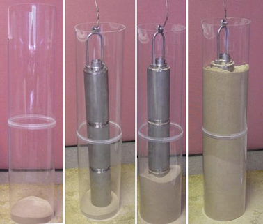
4.2 Installing a sensor using sand backfill
Dry sand backfill is a convenient and effective way of installing a borehole or post-hole sensor in a time-stable environment. The presence of sand not only fixes the sensor in place at the bottom of the hole, but also reduces noise due to air convection.
The ideal type of sand to use is the fine, kiln-dried sand used for children's play sandpits. This is readily available in airtight bags, is thoroughly washed and clean, and will contain little sediment. (When dried out after wetting, sand containing foreign matter may solidify and “concrete” the sensor in position.) This sand is suitable for use in both dry and damp boreholes.
In the procedure outlined below, the sensor rests on a pad of sand around 300mm thick. This pad will absorb any residual moisture at the bottom of the borehole, and ensure that the surroundings of the instrument are kept dry.
After positioning the sensor, more sand is added to fill the space between it and the borehole casing, holding it firmly in place. The sand should reach within 30mm of the top of the instrument, but should not cover it. This way, the instrument can be more easily recovered when it requires maintenance or replacement. This is particularly important if the borehole is not completely dry, since moist sand does not flow well.
The following photographs show the steps involved in backfilling with sand:
4.2.1 Procedure
To install a sensor at the bottom of a borehole of known depth using sand backfilling:
Measure or calculate the physical volume of the unit which is to be installed in the borehole. (The volume of a cylinder v = πr2h.) Also measure the internal diameter of the borehole.
Measure and pour in a sufficient quantity of sand to fill the borehole to a depth of around 300mm.
Connect the signal cable to the connector on top of the sensor. Ensure that the “O”-rings inside the housing are clean, and tighten the knurled connector nut to its end stop.

Fix the main lifting cable to the shackle on top of the strain relief mechanism, and run the signal cable through the mechanism using the built-in clamps (without tightening them.) Do not allow the signal cable to bear any of the sensor's weight.
Attach the lifting loop to the sensor using four M5×16 screws (provided).
Join the loop to the bottom of the strain relief mechanism using the linking cable provided.
Hoist up the sensor package and strain relief mechanism until both are hanging by the lifting cable, with the strain relief mechanism extended. Tighten the cable clamps on the strain relief unit, allowing a little slack in the signal cable.
Fix the signal cable to the main lifting cable about one metre above the strain relief mechanism using a metal clamp (a nylon cable tie may be sufficient for shallow installations.) Leave a little slack in the signal cable between the clamp and the strain relief mechanism.
Position the assembly over the top of the borehole. Do not allow it to drag across the ground.
Lower the sensor so that its base is level with the borehole mouth. Set the depth gauge on the winch to zero.
Calculate how much lifting cable must be lowered into the borehole, taking into account the length of the sensor and the strain relief assembly or digitizer.
If you are installing a 40TB in a deep borehole, the weight of the sensor will stretch the load bearing cable slightly. Remember to allow for this when raising or lowering the sensor in the following steps, since allowing the instrument to strike the bottom of the borehole will damage it.
Begin lowering the sensor down the borehole, keeping track of the depth reached.
At approximately 20 metre intervals, fix the signal cable to the load bearing cable using metal clamps (nylon cable ties every five metres may be sufficient for shallow installations). This will ensure that the signal cable does not become kinked or trapped within the borehole. Leave a little slack on the signal cable each time, so that it does not bear any weight. Too much slack, however, will cause the cable to scrape against the borehole casing.

Whilst monitoring the depth of the sensor, carefully approach the sand layer at the bottom of the borehole. The lifting cable will go slack when the sensor makes contact with the sand.
If the lifting cable goes slack before the sensor has reached the sand layer, it may have become caught on a bad joint or lip in the borehole; carefully raise and lower the instrument to free it.
When you have reached the bottom, use the winch to lift the package slightly, taking the slack off the cable. This ensures that the sensor is hanging vertically within the borehole, and is no longer in contact with the sand bed.
At this point, you may wish to use an inclinometer monitor unit to check that the instrument is sufficiently close to vertical to be properly centred.
Calculate the volume of dry sand required to fill the gap between the sensor and the borehole liner to the level of the top of the sensor (v = πr2h using the internal radius of the borehole, less the volume of the instrument determined in step 1.)
Pour this sand into the borehole. If you can, check how much of the sensor is covered with sand. Do not overfill the hole.
Carefully slacken the load bearing cable. This will engage the locking arm of the strain relief mechanism and secure the installation within the borehole.
Without pulling or lifting the sensor, lightly shake the cables to remove any sand that may have fallen onto them or onto the strain relief mechanism.
Clamp the load bearing cable to the top of the borehole, and remove the winch.
The sensor can now be levelled (see Section 4.5, page 38) ready for use.
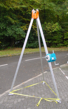
4.3 Assembling the winch
If required, Güralp Systems can provide a winch suitable for installing a borehole sensor. The winch and tripod are supplied as a set of parts which you can assemble on site:
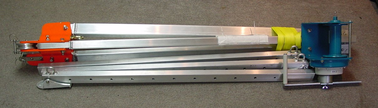
There are two sections for each leg of the tripod. The upper sections are pre-attached to the head of the tripod; the lower sections are supplied detached.
Slide the lower sections all the way into the head with the retaining tape loops facing outwards.
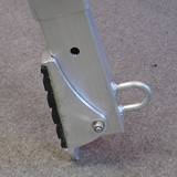
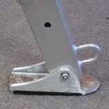
If you are working on a surface of sand or soil, rotate the feet so that the points face downwards (left). For rock or other hard surfaces, ensure the pads face downwards (right).
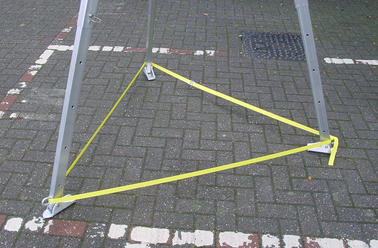
Erect the tripod above the borehole, and run the yellow retaining tape through the loops. Fasten together the ends of the tape.
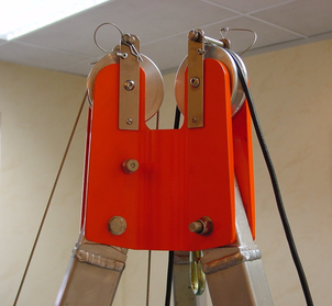
The lifting cable is supplied with a loop at one end. Run this over one of the pulleys at the top of the tripod, so that the loop hangs down between the legs. If the loop is not provided, you can make one by untwisting three outer strands from the (7-core) cable, crossing the two sets, and pleating the three outside strands back around the remaining four in the opposite direction. Secure the loop with a cable clamp.
Run the sensor signal cable through the other pulley. Secure both cables in their pulleys by sliding the attached bolts into place.
Extend each of the three legs in turn to the height you require, finishing at the leg with the winch attached.
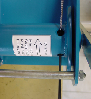
Take the end of the load-bearing cable without the loop, and screw it to the axle inside the winch using a 4 mm Allen key (provided) as shown.
Attach the handle to the side of the winch opposite the ratchet mechanism, and fasten it in place with a collar, washer and screw, using the larger Allen key.
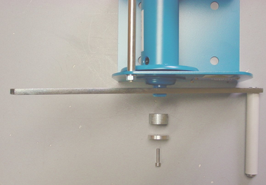
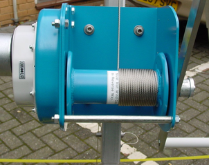
Wind the cable onto the winch by rotating the handle. Ensure that the cable builds up neatly across the drum. Continue winding until the loop on the other end is as high as you need it to install the equipment.
If the ratchet prevents you from winding the cable on, twist the metal boss in the DOWN direction to free the cable.
Remove the handle, and screw it onto the metal spool of the ratchet mechanism.
Hang the strain relief unit and instrument(s) from the loop at the other end of the cable. You are now ready to lower the assembly into the borehole as described above.
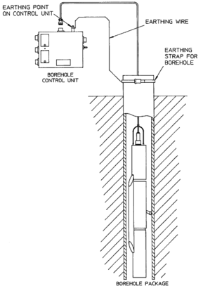
4.4 Earthing a borehole sensor
To achieve the best performance from any borehole instrument, you must make sure that the sensor electronics, its casing and the power supply share a common, local ground, and that all power and data lines are adequately protected against lightning and other transients.
This section describes techniques for grounding sensor equipment which have proved effective in many installations. However, local conditions are always paramount, and you should design your installation with these in mind. Any regulations in force at your chosen location must also be followed.
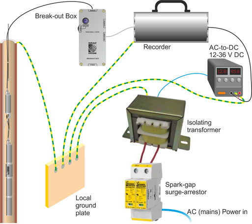
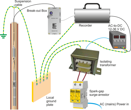
4.4.1 Installations with AC power supplies
If you are using mains (outlet) power, or some other AC power distribution system, we recommend installing a fully isolating transformer between it and the power supply for the instrument. This will allow full control of the local ground.
A spark-gap surge protector should also be installed on the mains side of the transformer, so that transient over-voltages are not transmitted across it. Suitable protectors are available off the shelf from several suppliers. On the sensor side, surge protection is installed as standard within all new Güralp borehole sensors and control equipment. If your surface installation includes third party electronics, digitizers, etc., you may need to install additional protection where power and data lines enter the surface enclosure. Contact Güralp Systems if you are unsure.
Within the installation, a single ground point should be established, which is connected to a local ground plate. All earth lines for equipment in the installation, such as the casings of the transformers and of the sensor electronics, as well as the signal ground line from the sensor, should be connected to this plate.
The best local earth point in many installations is the borehole itself. For this to work, the borehole must have a conductive casing and be situated close (<30 metres) to the surface installation. In such an installation you need only connect a cable (green wire in the photograph below) from the local ground plate to the borehole casing.
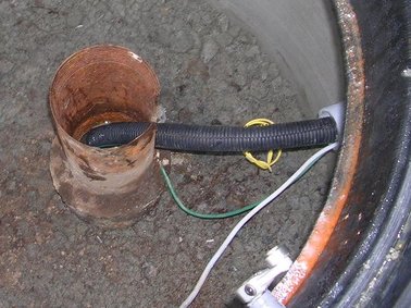
An earth strap can be used to ensure a good connection.
If the lower borehole is filled with salt water, the instrument will be adequately grounded without any further action. Fresh water is an inferior conductor.
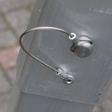
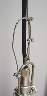
In a dry or sand-filled borehole, or one with a non-conducting casing, you will need to ensure the sonde is grounded by some other means. The best option is often to attach the sensor housing to an earth line brought out to the surface and attached to a metal stake driven into the ground nearby.
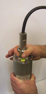
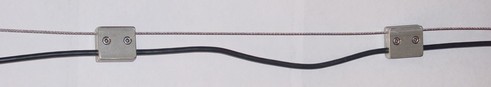
The sensor's load bearing cable is suitable for this purpose, provided it is secured to the sensor's lifting loop with a metallic clamp as shown below. This provides an additional firm contact between the sonde and the load-bearing cable. Installations with down-hole digitizers will need similar arrangements at the top and bottom of the digitizer module, or a separate cable for this purpose.
For boreholes with a metallic casing at the bottom and plastic above, we recommend connecting a cable between the sensor housing and the ground plate so that the lower borehole casing acts as the earthing point. Again, the
If there is a significant distance (>30 metres) between the borehole and the surface installation, the resistance of the earth cable may make it impractical to use the borehole as an earthing point. In these cases, you will have to connect the local ground plate to an earth stake near to the enclosure; any coupling between this sensor-local earth line and ground lines for other parts of the system must be minimized.
4.4.2 Installations with DC power supplies
Güralp sensors require a 24 V DC power supply. In most cases, this is provided by an isolating DC/DC converter installed at the surface. This converter can be earthed to the local ground plate as above.
However, DC/DC converters contain sensitive electronics, which must be protected thoroughly. We recommend installing a full surge protection unit in addition to the spark gap protector. This protection is installed on the supply side of the isolator, so it must be earthed separately from the borehole installation. Otherwise, transients in the power supply will couple to the sensor.
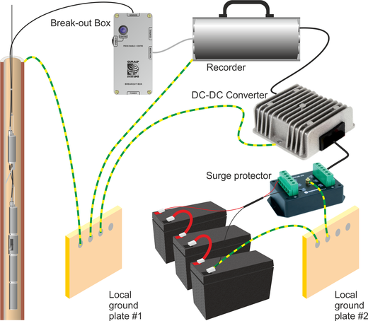
As with AC installations, if the borehole is more than around 30 metres from the surface enclosure, you will need to provide a second earthing point for the local ground plate.
DC power is most commonly available at self-contained installations with power supplied from batteries, solar panels, or a wind generator. In these cases, the power supply may already have protection from transients installed, in which case you may not need such comprehensive protection (although some form of protection is always necessary.)
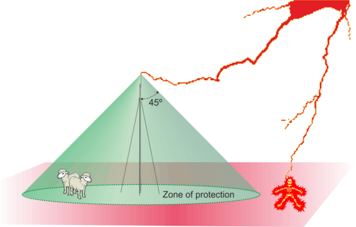
4.4.3 External lightning protection
The surface installation building and, if possible, the borehole should be protected by lightning conductors. These should lead to ground well away from the borehole. As a rule of thumb, a lightning mast provides a “zone of protection” within a 45 ° cone the height of the mast.
If you are using two earthing points, for example in the DC installation shown above, it may be convenient to connect the lightning conductor to the supply-side earthing point. In any case, the lightning earth must be well separated from the borehole (and its earth, if it needs one.)
4.5 Zeroing the instrument
The 40TB instrument will automatically level and null (zero) the mass position outputs on power up or when issued a centre command via the centre control line.
Internally the three sensors are mounted in gimbals that allow correction for all offsets of ±6° and up to ±8° in most directions. A microprocessor controls the locking and unlocking of these gimbals to level them, then makes an electronic adjustment via the feedback electronics to achieve a near zero mass position.
During a centre operation the output of the instrument may be seen to vary significantly as the gimbal mechanisms settle and the nulling occurs. Depending on the position of the sensors after installation, this process may be repeated up to three times and take around around six minutes to complete. If the instrument's tilt in the borehole is beyond the range of its centring capability it will continue with the closest setting to zero.
 After installation use a Hand-held Control Unit to observe the mass positions. These should be close to zero (within ±0.25 V), however the instrument should continue to operate normally with a mass position of up to ±4 V. This offset signifies that the instrument should be repositioned to correct the excessive tilt.
If the mass position drifts whilst the instrument is installed, centring can be triggered manually without the need of a power cycle. On the Breakout Box holding down both the centre and enable buttons simultaneously will trigger the instrument to centre all the sensors. Alternatively select the 'Centre' command of the DM24 digitizer.
4.6 Sensor orientation
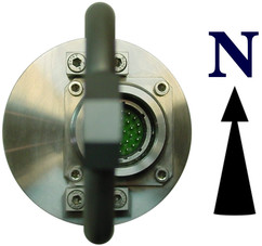 The orientation of the sensor is indicated by markings on the case
Labels are stuck to the case at the North point at the top and bottom of the tube and also on the base of the sensor.
In addition, because the lid connector is offset from the axis of the instruument, the North axis can be established from the following view in this photograph:
4.7 Down-hole orientation
Once the sensor is installed inside the borehole, you will need to measure its orientation with respect to the compass points. There is no need to rotate the sensor itself, since the data can be rotated algorithmically after it is digitised.
A simple method for determining the orientation of a sensor package using the sensor's own horizontal component sensors, has been used effectively by the Blacknest Seismological Centre, UK, with down-hole and surface equipment from Güralp Systems (AWE Report O 10/93, 1993.)
In this experiment, signals received by the N/S component of the reference sensor are correlated with those received at the N/S and E/W components of the sensor being studied, after different amounts of mathematical rotation. The highest correlation will occur when the N/S component of the reference sensor matches the rotated N/S component of the borehole sensor.
Once you know the deviation of the borehole components from the compass points, you can instruct the digitizer to rotate the signals algorithmically.
4.7.1 Installing the Scream! extension
The Relative Orientation extension is supplied in the standard Windows distribution of Scream! 4.2 and later.
The extension uses Matlab libraries, which are currently only available for Windows. However, you do not need the full Matlab package to use the extension. The Matlab runtime libraries are also included in the Scream! distribution.
4.7.2 Installing the reference instrument
To measure the orientation of a sensor, you will need a second instrument which is known to point precisely North. It should be located on a solid surface as close to the other instrument as possible. Most boreholes are constructed with a concrete base around the top of the borehole. If this is present, we recommend installing the reference sensor there.
Ideally, the two sensors will be directly connected to the same 6-channel digitizer. If you are using separate digitizers, you will need to ensure they are exactly synchronized. This can be done by connecting GPS receivers to both digitizers and waiting for the control system of each one to settle. This process takes at least 12 hours.
4.7.3 Measuring the orientation
Run Scream!. Open the File – Setup window, and select the Display tab.
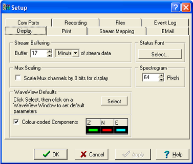
Under Stream Buffering, increase the buffer size to an amount which will hold all your experimental data. Click
 .
.Drag the data files you have recorded into Scream!. A Replay Control window will open.
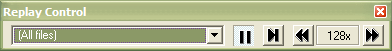
Click the Increase Speed icon
 until the legend (128x in the picture above) reads Max.
Click the Pause icon
 to begin replaying.
Scream! will be able to replay data faster if you are not currently displaying it. When Scream! has finished, the Replay Control window will disappear.
Hold down
 and select the N, E, and X streams from the digitizer at the correct sample rate.
The N and E streams are the “North/South” and “East/West” components of the down-hole instrument. The X stream is the North/South component of the reference instrument.
If you are using a separate digitizer, the reference instrument will appear on the North/South component of the other digitizer, instead of the X stream. To select this at the same time as the other streams, make sure Network is selected in the left-hand pane of Scream!'s main window, to display all the streams from your seismic network.
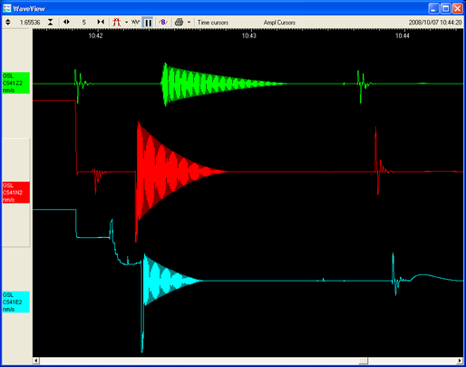
Double-click on one of the selected streams, or press ENTER. A WaveView window will open.
Drag the streams across the window so that the reference stream is at the top, the N stream in the middle, and the E stream at the bottom.
Click the Pause icon
 to stop the traces moving, and zoom in and out until you can see a suitable data range. You should use a period of at least an hour, and preferably longer.
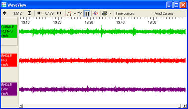
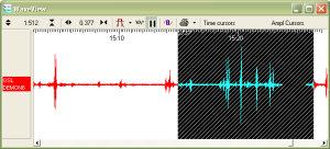
Hold down
 and drag across the WaveView window with the left button
  until all three streams are selected for the whole range.
Make sure there are no gaps in the data you select. In Scream! 4.3 and later, the selection will be shown with hatched lines if there is a gap:
When you are happy with the selection, release the mouse button, but keep
held down.When the menu appears, release the
key. Select Relative Orientation from the menu that appears.Two small windows will appear: a small progress window, and a warning with a legend like
Assuming DEMOX3 is reference N/S
Scream! produces this warning because the reference sensor is not using a standard N/S channel, but the auxiliary (X) channel.
If you are using a separate digitizer, the warning will not appear.
If you get an error, make sure the streams are in the right order in the WaveView window. If you still have problems, you may have selected too few data points for it to be confident about the orientation; you should try again with a larger selection, or when more data is available.
After a few seconds, the calculation should finish and two windows will appear. (One may obscure the other.)
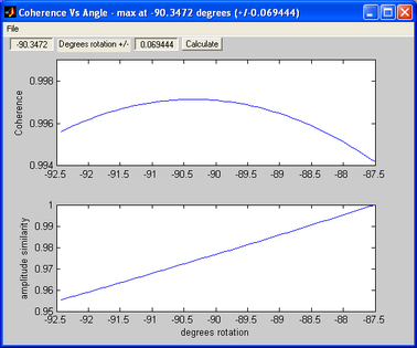
The top window is a graph of Coherence vs Angle:
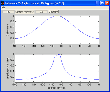
The two-stage algorithm rotates the N/S and E/W components of the sensor being tested in small steps.
It measures first the amplitude similarity, and then the coherence between this new N/S component and the reference N/S component, for a number of rotation angles.
The error in the final calculation is around 2.5 °.
The peak of the coherence curve (upper graph) therefore corresponds to the angle of rotation which best matched the reference component. This angle is shown in the title bar, together with an estimated error.
You should see a coherence curve which is smooth and symmetrical. If the curve is distorted, either the surface data is too noisy or the data selection is too short.
The lower graph shows the overall amplitude similarity of the rotated signal. This provides an idea of the sign of the coherence (since signals in perfect antiphase have a high coherence as well as those in phase). If there are two peaks in the coherence graph, the correct one is where the amplitude similarity is most positive.
The sample plots show that the borehole instrument is installed with its N/S axis at a bearing of –90 ° from true North.
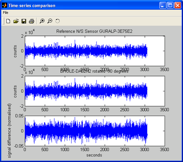
The second window shows the result of applying the rotation to the signal, i.e. the time series that a sensor in perfect N/S orientation would have produced:
You can perform more accurate calculations by narrowing the search range. This is done in the two entry boxes on the Coherence vs Angle window: the first denotes the centre of the new search, and the second its range.
The program suggests suitable values for you, so in most cases you can just click
 to perform another iteration.
A new graph will be displayed showing the results:
Our sample instrument is thus aligned at –90.35 ± 0.07 °.
The error given is only a rough estimate. You should repeat the orientation experiment several times using different data sets. The true error in the computed orientation can be determined by observing the spread of the results.
The Blacknest orientation method generally provides a reliable indication of the sensor's orientation. In most cases, the greatest source of error is in the installation of the reference sensor.
4.7.4 Applying automatic rotation
You can configure a DM24 mk3 digitizer to apply an automatic rotation to the digitized data and output streams representing ground motion on true North/South and East/West axes.
This is done within the DSP to minimize the reduction in data quality.
To set up the rotation:
Open a terminal session with the digitizer. You can do this with a program such as minicom (for Linux) or PuTTY (for Microsoft Windows). Alternatively, you can access the digitizer's console through Scream! by right-clicking on its icon (
 ) and selecting Terminal....
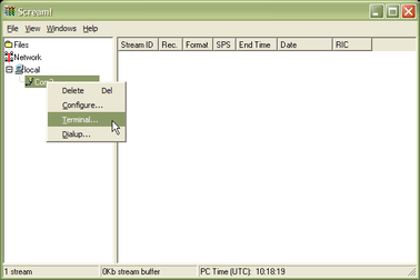
You should see an ok prompt, indicating that the digitizer is ready to receive commands.
Type
0 rotation AZIMUTH
where rotation is the angle of deviation from true North that you measured earlier, as a whole number of tenths of a degree. This is the same angle (with the same sign) as that given by the orientation program.
The 0 tells the digitizer to apply the rotation to instrument number 0 (the first, or only instrument.)
Thus in the example above, you would type 0 -903 AZIMUTH to make the digitizer rotate signals by –90.3 degrees.
Reboot the digitizer with the command re-boot.
Collect some more data with the transformation active, and carry out another orientation calculation. The data from the down-hole instrument should now have a maximum coherence with the reference sensor at 0 °. Check in particular that the sign of the rotation you have applied is correct.