Chapter 4. Appendices
4.1 Appendix A - Default Settings
4.1.1 Lantronix WiPort NR Default Settings
Parameter | Setting |
Network | |
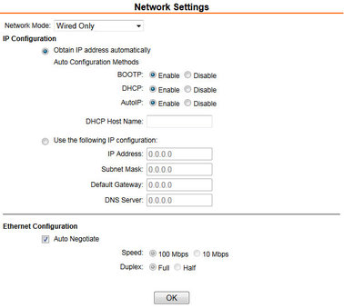
Network mode | Wired Only |
IP Configuration | Obtain IP address automatically |
Ethernet Configuration | Auto Negotiate |
Server | |
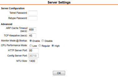
Server Configuration | Passwords: Leave blank |
Advanced | ARP Cache Timeout: 600 seconds |
Hostlist | |
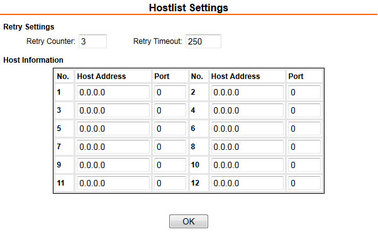
Retry Settings | Retry Counter: 3 |
Host Information | All set to zero |
Channel 1 and 2 Serial Settings | |
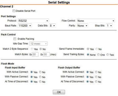
Disable Serial Port | Leave un-ticked |
Port Settings | Protocol: RS232 |
Pack Control | Enable Packing: leave un-ticked |
Flush Mode | All set to No |
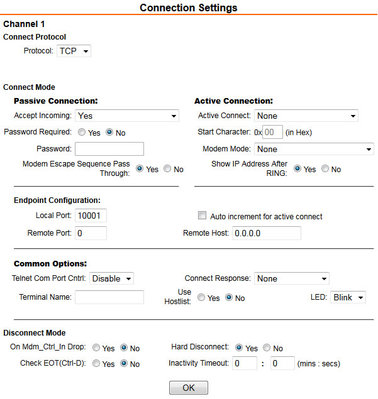
Channel 1 and 2 Connection Settings | |
Connection Protocol | TCP |
Connect Mode | Accept Incoming: Yes |
Endpoint Configuration | Local Port: 10001 for Channel 1 |
Common options | Telnet Com Port Cntrl: Disable |
Disconnect Mode | On Mdm_Ctrl_In Drop: No |
NA | |
Configurable Pin Settings | NA |
4.1.2 Lantronix WiPort NR Default Settings Screenshots
4.1.2.1 Network settings
4.1.2.2 Server settings
4.1.2.3 Hostlist settings
4.1.2.4 Serial settings
4.1.2.5 Conenction settings
4.1.3 EAM Fast Port Default Settings
Parameter | Setting |
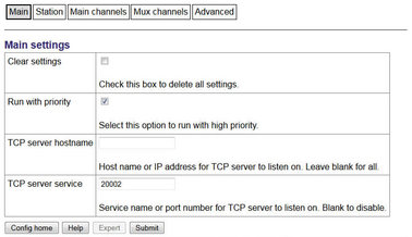
Main | Clear settings: Leave un-ticked |
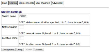
Station | Station name: Mandatory (shipped with the serial number of the EAM). If a common station name is used for a number of sensors an additional location name is required to ensure a unique identifier. |
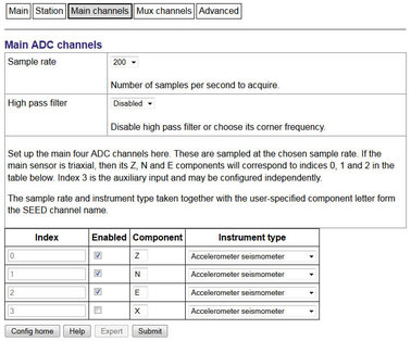
Main channels | Sample Rate: 100 |
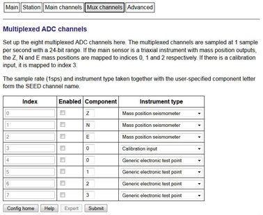
Mux channels | Component/Instrument Type |
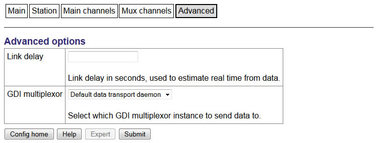
Advanced | Link delay: Leave blank |
4.1.4 EAM Fast Port Default Settings Screenshots
4.1.4.1 Main
4.1.4.2 Station
4.1.4.3 Main channels
4.1.4.4 Mux channels
4.1.4.5 Advanced
4.2 Appendix B - Lantronix WiPort NR Device Manager
The acquisition module uses an embedded Lantronix Wi-Port module to provide the low-latency network interface. The device can normally be accessed using a web-interface as described in section 3.2.
If this is not possible configuration of the interface can be carried out using the Lantronix' DeviceInstaller utility for Microsoft Windows, using a DHCP server or the via the serial port. You will need a PC with a network interface installed or an RS232 connector.
Note: Refer to Appendix E on page 31 for information on connector pinouts.
Download and install the DeviceInstaller utility from the Lantronix Web site at www.lantronix.com.
DeviceInstaller requires the Microsoft .NET framework to be installed. If you do not have this already, it can be downloaded from: www.microsoft.com.
Note that DeviceInstaller will not work through routers or across the Internet. All the devices need to be on the same network segment as the PC.
Find out the MAC address of the network interface. This should be printed on a label on the case.
Connect the 6-pin Ethernet port to the the PC's network interface either using a crossover Ethernet cable or through a network hub. Note that using a hub, you can connect several CD24s to the same PC and configure them all at the same time.
Use the power cable to connect the 4-pin power connector to a fused 10 – 28 V power source. A 12V DC power supply is recommended.
Run DeviceInstaller.
DeviceInstaller's main window has two panels, a tree on the left (with Lantronix Devices at the top) and a table on the right.
The program will automatically look for Lantronix devices on all of your computer's network interfaces. If necessary, you can narrow the selection by clicking on an entry in the tree on the left. If the program does not list the device, press F5 or use Device > Search from the menu system.
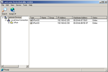
A WiPort NR entry should appear in the table on the right, denoting that a device has been detected.
If more than one WiPort NR entry appears, DeviceInstaller has detected several devices.
For every detected device, the program shows the Hardware Address (i.e. the MAC address) and the IP address it is currently using. If you are using a wireless router with a DHCP server, or an access point connected to a network with a DHCP server, the device will use DHCP to assign it an address. Otherwise, a random address will be chosen automatically.
Note: Automatic random addresses all begin with 169.254. The CD24 will choose a different one every time it is power cycled or rebooted.
The address of the CD24 may be shown in red with the status Unreachable. If this happens, the sensor and PC cannot communicate because they are not on the same subnet. Click Assign IP to start the IP configuration wizard. Follow the instructions in the wizard to set the IP address, or configure DHCP if you are using a DHCP server. When you have finished, press F5 or use Device > Search from the menu system to find the sensor with its new IP address.
Note: The IP address of the digitiser must have be on the same subnet as the computer you want to connect to. The LAN setting on the DeviceInstaller device tree identifies the IP address of your computer. The first three number groups typically need to be the same on all devices (digitisers and computer).
If you want to configure the CD24 to use a static IP address, use the Assign IP wizard as above and click Search again.
Double-click on the entry which corresponds to the CD24 you want to configure. The right-hand panel will change to show the current properties of the device.
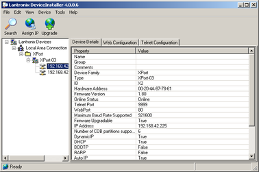
Switch to the Web Configuration tab and click Go to open the Web configuration interface.
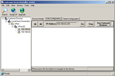
You can also click Use External Browser to use your own Web browser to configure the system.
Follow the steps at section 3.2 on page 7.
4.3 Appendix C - Advanced network configuration
The Lantronix WiPort NR networking module has serial-accessible configuration systems which can be used to configure them in the event that communication over a network is lost.
If you have problems connecting to the CD24 over a network, you can access the configuration menu over a serial link by interrupting the boot process. See the following section for instructions. For full information about the WiPort NR configuration options, which are used during the process, please refer to the relevant documentation, which is available on the Lantronix Web site: www.lantronix.com. The detailed documentation is at: www.lantronix.com/pdf/WiPort-NR_UG.pdf
4.3.1 Accessing the configuration menu via the serial Interface
Access to the configuration menu over the serial interface can be obtained using any serial terminal emulator (see Appendix D on page 26).
The procedure for connecting to the device is:
Disconnect the power supply.
Disconnect the sensors.
Remove the top cover from the acquisition module.
Disconnect the 26-way IDE-connector from the digitiser as indicated in the figure below:
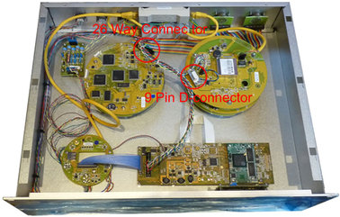
Connect an RS232 cable between the 9-pin D-connector and a PC. See Appendix E on page 31 for connector pinouts.
Open a terminal connection as described in Appendix D on page 26.
Hold down the
 key while applying power to the acquisition module.
After a few seconds, a banner will appear, showing the MAC address of the network interface, along with software and library version information. Press the Enter key to access the set-up menu. If you do not press a key, the system will proceed to boot normally.
4.3.2 Configuring the network interfaces
Once you have access to the networking module's configuration menu, you can configure it with its proper settings.
During the configuration process, you are prompted, in turn, for every value in the current section. If you are unsure at any point, pressing the Enter key will retain the current value. Please note that many values need to be entered using special codes. These are all documented in the relevant Lantronix manuals.
From the main menu:
Each channel is configured individually. To configure either press 1 (Channel 1) or 2 (Channel 2).
Set the Baud Rate to 115200. This is the default baud rate for the CD24's digital output.
The remaining settings can be left at their default values, which is done by pressing Enter at each prompt until you are returned to the main menu.
When you have finished setting up the module, apply the new settings by selecting option 9 Save and Exit. The module will re-boot with the new settings in effect.
4.3.3 Configuring the Ethernet port
To configure the Ethernet port
If DHCP is not being used to assign IP addresses, enter the required address manually. The IP address must be set to a unique value in the network. Enter each octet and press Enter to move to the next octet.. The current value is displayed in parentheses. If you do wish to use DHCP, enter 0 at each prompt (an IP address of 0.0.0.0 is used to select DHCP operation).
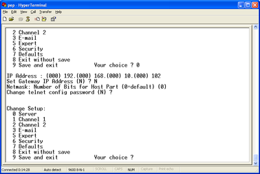
If the digitiser is to be connected to a routed network, enter the address of the default gateway in the same manner.
At the netmask prompt, enter 0 if you are using normal (classful) internet addressing. If you have a non-standard or classless addressing scheme, enter the number of bits of the IP address to be used for network identification. Note that this is not the standard way of specifying netmasks; it is more akin to the /n modifier used in CIDR address specification.
When you have finished setting up the module, apply the new settings by selecting option 9 Save and Exit. The module will re-boot with the new settings in effect.
Disconnect the power supply from the acquisition module.
Remove the RS232 cable from the 9-pin D-connector.
Connect the 26-way IDE-connector to the digitiser.
Install the top cover.
Connect the sensors to the acquisition module.
Connect the power supply to the acquisition module.
4.4 Appendix D - Using terminal emulators
There are a number of terminal emulator programs that you can use to access the serial ports of the digitiser and networking interfaces. Three of these are detailed below.
4.4.1 Hyperterminal, as provided with Windows XP.
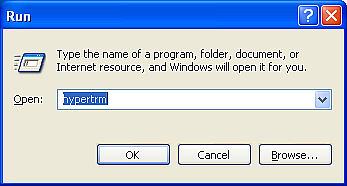
Click on Start and then Run.
Enter 'hypertrm' and click on OK.
The program will ask you for a name for the connection:
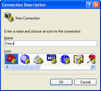
Enter any suitable name, then click OK.
You will then be prompted to enter COM port and modem details:
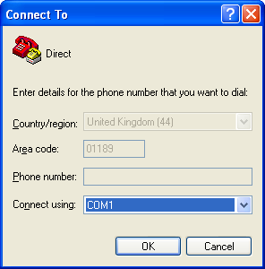
The Country/region, Area code and Phone number fields can be ignored: they are only used when working with modem connections. Select the name of the correct COM port from the Connect using drop-down menu, then click OK.
Enter the port configuration settings:
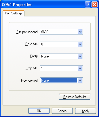
Ensure the following parameters are set:
Bits per second: 9600
Data bits: 8
Parity: None
Stop bits: 1
Flow control: None
Click on OK and the program will then connect provide you with a terminal emulator screen, from which you can access the command line of your system.
4.4.2 Using Hyperterminal with Windows Vista or Windows 7.
HyperTerminal is not provided with the Windows Vista or Windows 7 operating systems but the necessary files can be copied from the i386 directory of the Windows XP CD if you have one available. The two files you will need are:
hypertrm.dll
hypertrm.exe.
If you do not have a Windows XP disc the files can be downloaded from: www.mediafire.com
To use Hyperterminal with Windows Vista or Windows 7:
Copy the two files into your windows/system32 directory.
To access HyperTerminal, use Windows+R on your keyboard. Enter 'hypertrm' and click on OK.
If Windows open a security warning window click on Run. You may also be asked if you wish to use HyperTerminal as a the default terminal window.
Now follow the instructions given in section 4.4.1, above.
4.4.3 Using PuTTY.
PuTTY is a free terminal package for windows which is useful if HyperTerminal is not available. It can be downloaded from www.chiark.greenend.org.uk. The easiest package to use is the 'windows installer'. Install PuTTY by following the on-screen instructions.
Start PuTTY by clicking on the desktop icon or Start-menu entry
Click on Serial at the bottom of the category menu on the left:
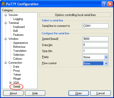
Select a serial line to connect to. This is usually COM1.
Configure the serial line with the following settings:
Speed (baud): 9600
Data bits: 8
Stop bits: 1
Parity: None
Flow control: None
Click on Session in the main menu on the left.
In the right hand part of the window use the radio buttons to select the Serial Connection type. Check the Serial line and Speed fields are correct:
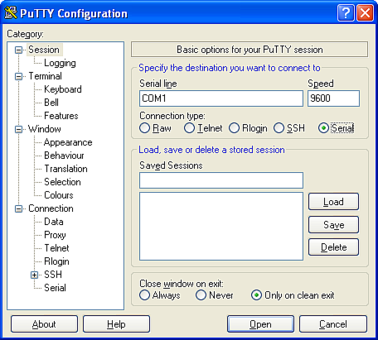
To save the settings enter a suitable session name in the Saved Sessions field then click Save.
The next time you start PuTTY, your saved session will appear in the list and you can simply double-click it to open a new session with the same settings.
Click the Open button to start the terminal emulator.
4.5 Appendix E - Connector pinouts
4.5.1 SENSOR A & B
This is a standard 26-pin “mil-spec” plug, conforming to MIL-DTL-26482 (formerly MIL-C-26482). A typical part-number is 02E-16-26P although the initial “02E” varies with manufacturer. Suitable mating connectors have part-numbers like ***-16-26S and are available from Amphenol, ITT Cannon and other manufacturers. |
|
Pin | Function | Pin | Function |
A | Vertical velocity +ve | P | Calibration signal |
B | Vertical velocity –ve | R | Vertical calibration enable |
C | N/S velocity +ve | S | N/S calibration enable |
D | N/S velocity –ve | T | E/W calibration enable |
E | E/W velocity +ve | U | Centre |
F | E/W velocity –ve | V | Active-high |
G | Vertical mass position | W | Unlock |
H | not connected | X | Lock |
J | N/S mass position | Y | Logic signal ground |
K | Busy indicator LED | Z | not connected |
L | E/W mass position | a | not connected |
M | not connected | b | Power 0 V |
N | Signal ground | c | Power +10 to +24 V |
| Wiring details for the compatible socket, ***-16-26S, as seen from the cable end (i.e. during assembly). |

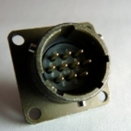
4.5.2 GPIO
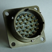
These are standard 12-pin “mil-spec” sockets, conforming to MIL-DTL-26482 (formerly MIL-C-26482). A typical part-number is 02E-14-12S although the initial “02E” varies with manufacturer. Suitable mating connectors have part-numbers like ***-14-12P and are available from Amphenol, ITT Cannon and other manufacturers. |
|
The USB lines provide external host access to the internal USB memory device. When power is sensed on pin J, an internal switch disconnects the memory device from the internal circuitry and connects it to this socket.
Pin | Function |
A | USB Data -ve (USB Type A pin 2) - see text above. |
B | USB Data +ve (USB Type A pin 3) - see text above. |
C | Anti-tamper line 4 |
D | Anti-tamper line 3 |
E | Anti-tamper line 2 |
F | Anti-tamper line 1 |
G | Console transmit (RS232 TXD) |
H | Console receive (RS232 RXD) |
J | USB Power input (USB Type A pin 1) - see text above. |
K | Ground (USB Type A pin 4) |
L | Anti-tamper line 0 |
M | Ground |
| Wiring details for the compatible plug, ***-14-12P, as seen from the cable end (i.e. during assembly). |
4.5.3 GPS
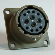
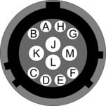
This is a standard 10-pin “mil-spec” plug, conforming to MIL-DTL-26482 (formerly MIL-C-26482). A typical part-number is 02E-12-10P although the initial “02E” varies with manufacturer. Suitable mating connectors have part-numbers like ***-12-10S and are available from Amphenol, ITT Cannon and other manufacturers. |
|
Pin | Function |
A | Power 0 V |
B | Power +12 V |
C | 1pps signal |
D | not connected |
E | Digitizer console transmit |
F | Digitizer console receive |
G | RS232 ground |
H | Digitizer console ground |
J | RS232 transmit to GPS |
K | RS232 receive from GPS |
| Wiring details for the compatible socket, ***-12-10S, as seen from the cable end (i.e. during assembly). |

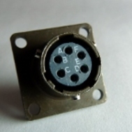
4.5.4 USB
This is a standard 6-pin “mil-spec” socket, conforming to MIL-DTL-26482 (formerly MIL-C-26482). A typical part-number is 02E-10-06S although the initial “02E” varies with manufacturer. Suitable mating connectors have part-numbers like ***-10-06P and are available from Amphenol, ITT Cannon and other manufacturers. |
|
Pin | Function |
A | +5 V DC (USB Type A pin 1) |
B | Data –ve (USB Type A pin 2) |
C | Data +ve (USB Type A pin 3) |
D | 0 V (USB Type A pin 4) |
E | Shielding |
F | not connected |
| Wiring details for the compatible plug, ***-10-06P, as seen from the cable end (i.e. during assembly). |

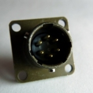
4.5.5 Ethernet
This is a standard 6-pin “mil-spec” plug, conforming to MIL-DTL-26482 (formerly MIL-C-26482). A typical part-number is 02E-10-06P although the initial “02E” varies with manufacturer. Suitable mating connectors have part-numbers like ***-10-06S and are available from Amphenol, ITT Cannon and other manufacturers. |
|
Pin | Function |
A | Ground |
B | Data transmit +ve (RJ45 pin 1) |
C | Data receive +ve (RJ45 pin 3) |
D | not connected |
E | Data receive –ve (RJ45 pin 6) |
F | Data transmit –ve (RJ45 pin 2) |
| Wiring details for the compatible socket, ***-10-06S, as seen from the cable end (i.e. during assembly). |

4.5.6 Power/Data Out
This is a standard 10-pin “mil-spec” plug, conforming to MIL-DTL-26482 (formerly MIL-C-26482). A typical part-number is 02E-12-10P although the initial “02E” varies with manufacturer. Suitable mating connectors have part-numbers like ***-12-10S and are available from Amphenol, ITT Cannon and other manufacturers. |
|
Pin | Function |
A | Power input, 0 V |
B | Power input, +10 to +36 V |
C | RS232 CTS |
D | RS232 RTS |
E | not connected |
F | not connected |
G | RS232 ground |
H | not connected |
J | RS232 receive |
K | RS232 transmit |
| Wiring details for the compatible socket, ***-12-10S, as seen from the cable end (i.e. during assembly). |
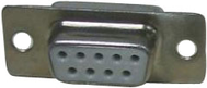
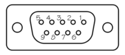
4.5.7 Lantronix WiPort NR D-Connector
These are standard DE9F (TIA-574) sub-miniature (D-sub) line sockets, conforming to DIN 41652 and MIL-DTL-24308. They are very widely available, as are suitable mating connectors. |
|
Pin | Function |
1 | not connected |
2 | RS232 transmitted data* |
3 | RS232 received data* |
4 | not connected |
5 | Ground |
6 | not connected |
7 | not connected |
8 | not connected |
9 | not connected |
| Wiring details for the compatible plug, DE9M, as seen from the cable end (i.e. when assembling). |
4.6 Appendix F - Specifications
Parameter | Specification |
Input range | ±10V differential |
Nominal Sensitivity | 0.9µV/count |
Standard output format | 24-bit |
Noise-free resolution (NPR) at 20 samples/s | > 132 dB r.m.s. (> 22 bits) |
Digital signal processor | TMS3200 at 144 MHz |
Output latency | <100ms at 100sps (low latency port only) |
Output baud rate | 115200 |
Operating temperature range | –10 to +75 °C |
Internal thermometer accuracy | ±0.33 °C (30 °C) |
Internal thermometer linearity | ±0.5 °C |
Internal thermometer resolution | 0.0625 °C |
Dimensions | 483 x 280 x 89mm (excluding connectors) |
Weight | 1.95kg |
Voltage requirements | 10..24V DC |
Current at 12 V DC with GPS | 270 mA |
4.7 Appendix G - Revision history
24 May 2011 | A | New document |