Chapter 7. Inside the 3ESPCD
7.1 Inside the 3ESPCD
7.1.1 The sensors
The horizontal and vertical sensors are similar in design. The inertial mass in both cases consists of a transducer coil and a leaf-spring suspended boom which swings on a frictionless hinge. A triangular spring supports the weight of the mass; in the vertical sensor this spring is pre-stressed, with a natural period around half a second, whilst the horizontal sensor has an unstressed flat spring with a natural period around 1 second. Güralp3ESPCD sensors have no spurious resonances below 140 Hz, and weigh around 180 g. The small boom size and stiff springs allow three independent instruments to be mounted within the casing, together with all the associated feedback electronics.
The 3ESPCD functions by monitoring the position of each mass with a capacitative position sensor. The three sensors are identical. Signals from the sensors are fed into an electronic processing unit, which is mounted in a screened compartment above the mechanical components (see below for details on the feedback circuitry.)
When the instrument is being transported, the masses are locked securely in their frames so as to relieve strain on the support hinges. This locking is performed by a small motor-driven clamp in response to a signal from the surface controller unit.
Before using the instrument, the boom of the vertical sensor must be levelled and the bases of the horizontal sensors tilted, so that the masses are centred in their equilibrium positions. These adjustments are made by small DC motors controlled remotely.
See section 3 for detailed instructions on how to set up your 3ESPCD installation.
The signal voltages output by the 3ESPCD are proportional to ground velocity, and are transmitted from the instrument on balanced differential lines. In addition, mass position signals are sent as single-ended circuits referred to analogue ground on the output plug. The 3ESPCD also receives control signals, which are used to clamp and un-clamp the masses, and to run the motors which level and centre the instrument once in position. Finally, a line is provided for you to apply a calibrating voltage to the force transducers, thereby measuring the deflection sensitivity.
7.1.2 The control system
The internal operations of the 3ESPCD are supervised by a control microprocessor, which drives the mass clamping and centring adjustment motors. It responds to commands sent on three input lines. To activate a line, it should be grounded to digital ground for seven seconds. The delay is to prevent accidental activation. The signals sent to the microprocessor are termed LOCK, UNLOCK, and CENTRE. Each command acts on the vertical, N/S and E/W masses in turn. The microprocessor prevents the system from attempting incompatible actions (e.g. centring when the masses are locked).
While a command is taking place, the BUSY LED will flash; you can use this for diagnostic purposes. See the description of each command for full details.
When no command is active, i.e. all three lines are high, the control microprocessor goes into a power-saving mode. In integrated instruments, such as the 3ESPCD, the lines are controlled by the digitiser.
7.1.2.1 LOCK
This command locks the vertical mass and clamps the horizontal sensors by tilting them up to their end stops. If LOCK is activated when the masses are already locked, the processor will unlock them and attempt to lock again. This is useful if you suspect that the locking procedure has failed.
In detail, the process acts as shown in the following graph. The top three streams are the mass position outputs of each component (Z, N/S and E/W, respectively), whilst the bottom one represents the state of the BUSY LED (up = on).
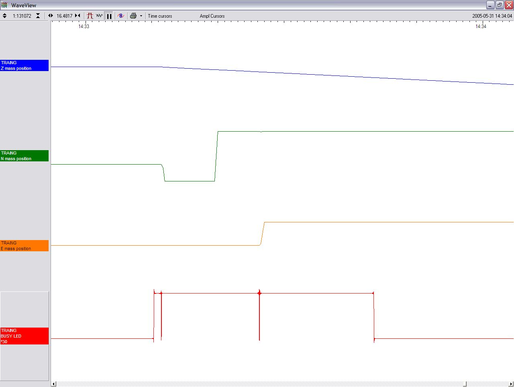
In the three-stage process, the vertical mass is locked with a motorised micrometer, and the N/S and E/W sensor bases are tilted to their end stops. At some point during each tilting stage, the position of the relevant mass will flip to one or other side. With the horizontal bases tilted, gravity will keep the masses pressed against their end stops, effectively locking them in place. Because the 3ESPCD mass assembly is designed for a degree of robustness, no further locking is required.
The BUSY LED is lit during each stage, but goes out briefly between stages, allowing you to follow the progress of the lock.
7.1.2.2 UNLOCK
This command unlocks the sensor masses and prepares the instrument to begin operating. If UNLOCK is activated when the masses are already unlocked, the processor will lock them and attempt to unlock again. This is useful if you suspect that the locking procedure has failed.
During the UNLOCK procedure, the instrument automatically performs a round of centring for each component. Again, you can use the BUSY LED to monitor the progress of unlocking.
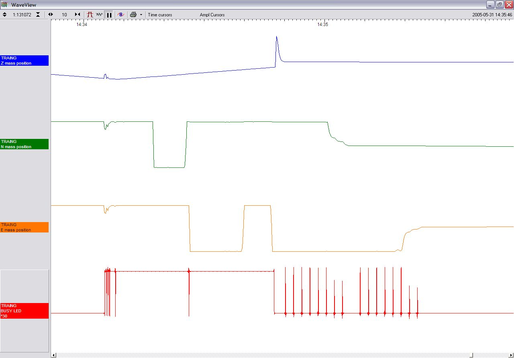
As shown, the process is:
The instrument checks to see whether the vertical mass is locked, and unlocks it if necessary.
The vertical mass is centred by applying pulses to the motor. This stage is often very short, since the vertical mass is locked near its central position.
The instrument checks the N/S sensor and base, and unlocks the sensor.
The N/S sensor base is tilted to its level position. This process takes rather longer. At some point during this stage, the mass may flip to the other side (as seen in the green trace.)
The N/S sensor mass is centred by applying pulses to the motor. This stage will take longer than stage 2, since it must move the mass all the way from its end stop. As the mass nears the centre, the control circuit spaces out the pulses.
The E/W component is checked and unlocked.
The E/W sensor base is tilted to its level position as in step 4.
The E/W sensor mass is centred as in step 5. After unlocking, the instrument automatically performs a round of centring (see below).
7.1.2.3 CENTRE
This command re-centres the masses. If the masses are clamped, or if the sensor mass positions do not exceed ± 1.2 V, the CENTRE command does nothing. Otherwise, it attempts to zero the output of the vertical, N/S and E/W sensors in sequence by exerting small extra forces on the boom.
For the vertical sensor, a motor-driven adjuster presses a small spring lever against the boom until the mass position sensor indicates an offset close to zero. In the case of the horizontal sensors, the sensor frame is tilted on its base plate. Again, the controller monitors the mass position sensor and stops the centring process once it reaches its lowest offset.
This graph shows a typical centring process:
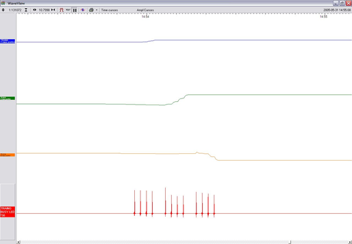
The BUSY LED pulses to indicate that it is centring the Z component. Each pulse corresponds to a small force on the mass. The pulses become briefer as this goes on, until a pulse is missed, signifying that no corrective impulse is needed.
The N/S component follows in the same way. If the true mass position is outside the range of the output, you may not see the output change for some time. If the pulses cause the mass to overshoot the central position, a second group of pulses in the opposite direction is applied to bring it into line.
The E/W component follows in the same way. All three masses are now centred and the process completes.
After the sensor unlocks the masses, the first round of centring has to move the N/S and E/W components all the way from their end stops, whilst the Z component is often closer to the proper position. Because of this, the first Z centring operation takes much less time than the others, and you may not notice it.
After successful centring, the mass position outputs should be in the range 0.1 – 0.8 V. If the centring process leaves the mass position outputs above ±1.1 V, you should start another centring cycle by activating the CENTRE command again. You will probably need to initiate the centring process several times before the masses are adequately centred.
7.1.3 The feedback system
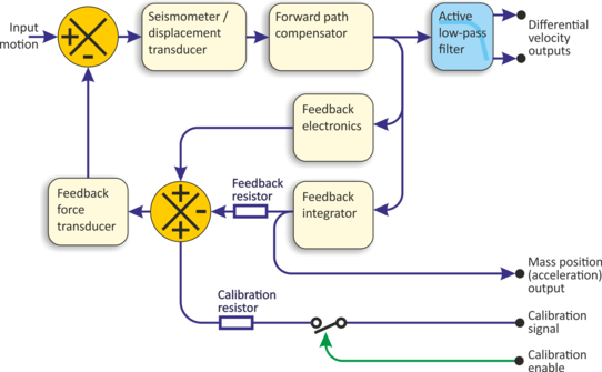
The output from a modern broadband seismometer does not depend on the natural characteristics of the instrument. Instead, the period and damping of the sensor is completely determined by a feedback loop which applies a force to the sensor mass opposing any motion. The force required to restrain the movement of the mass can then be used to measure the inertial force which it exerts as a result of ground motion.
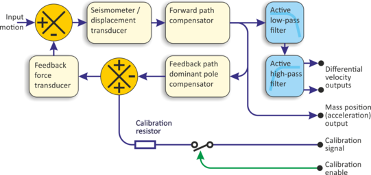
All 3-series units are based on these general principles. The capacitative position sensor for each mass produces a voltage proportional to the displacement of the mass from its equilibrium position. After amplification, this voltage generates a current in the force transducer coil which tends to force the mass back toward equilibrium. The feedback loop has a sufficiently high gain to cancel the motion of the mass. Since the mass is not moving, the forces acting on it must be balanced; the feedback voltage then directly measures the force, and hence the acceleration, which is being applied to the mass. The feedback loop introduces a phase shift, which must be carefully controlled if the instrument is to remain stable over its entire frequency range. This is achieved using compensation components in the forward and feedback paths.
Force feedback seismometers of this type rely on the assumption that the force transducer produces a field of constant strength. The magnetic circuit and magnet/pole assembly in the Güralp 3ESPCD are designed so that the field strength from the feedback transducer is constant over large deflections and current levels.
In a force-feedback seismometer, it is essential to monitor the acceleration output. This provides the position of the inertial mass. The sensor should always be operated with the mass centred, so that the response to input acceleration is linear.
There are two types of feedback system which can be used in a 3ESPCD instrument, known as hybrid and conventional-response feedback.
7.1.3.1 Hybrid feedback
The hybrid feedback circuit contains a single capacitor in parallel with a resistor, resulting in a single dominant pole at 0.033 Hz (30 seconds). Below this frequency, the response of the seismometer is flat to ground acceleration; above it, the response is flat to velocity. (Other values for the acceleration-velocity corner can be provided upon request.)
Hybrid-feedback systems provide a stable response, particularly for portable systems, with a high saturation level at high frequencies and a high dynamic range at long periods. An active low-pass filter provides a high-frequency cut-off point at a frequency you specify. Without the filter, the velocity response is flat up to 100 Hz. Outside the feedback loop, there is an active high-pass filter with a corner frequency of 0.01 Hz (100 s) or 0.005 Hz (200 s), which serves to remove any DC offsets.
7.1.3.2 Conventional-response feedback
The conventional-response feedback system has an additional parallel feedback circuit, consisting of a non-inverting integrator in series with a resistor.
This arrangement results in two poles at specified frequencies. The velocity response of a conventional-response system is defined by a transfer function identical to that of a conventional long-period sensor with a damping constant ζ of 0.707 (1/√2).
The seismometer can be supplied with an equivalent resonant frequency of 0.033 Hz (30 s), 0.01 Hz (100 s) or 0.0083 Hz (120 s) as required. An active low-pass filter provides a high-frequency cut-off point at a frequency you specify.
7.1.3.3 Comparisons
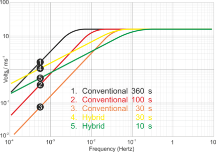
The figures below plot the comparative response of a conventional velocity output broadband sensor and a hybrid output broadband sensor.
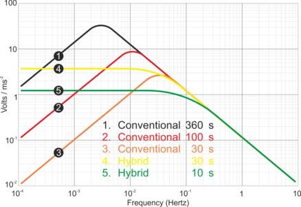
The graph above shows the response in terms of output against input acceleration in units of V/ms-2, whilst the second graph is plotted in terms of output against input velocity, in V/ms-1.
7.2 Inside the DM24
7.2.1 Architecture
Internally, DM24 digitisers are structured as shown in the following diagram.
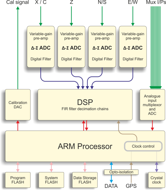
The system is designed around a low power, high performance ARM microprocessor. This is a 32-bit processor with a large address space for data storage and manipulation. It also includes many integrated functions such as multiple timers and serial I/O ports. In addition, the system contains a Cirrus Logic CS5376 digital filtering chip-set and TMS320VC33 digital signal processor (DSP). The CS5376 provides data to the DSP at 2,000 samples per second, triggered by timing signals from the ARM processor. The DSP can control all 5 ADCs and process the data in real time.
An important feature of the system design is its ability to synchronise the sampling of the analogue to digital converter to an external time reference. This way, data samples are accurately time stamped at source. To keep sampling accurately in step with UTC, you can synchronise the microprocessor's time-base to an external reference such as GPS or, in larger arrays, to a centrally-transmitted time reference. Transmitting a time reference avoids the cost and power consumption of multiple GPS receivers, and since it only involves sending 2 characters per second it can utilise a low band-width, even half-duplex link.
To achieve the high degree of timing precision required for a 24-bit digitiser system, the microprocessor time-base is run from a precision voltage controlled oscillator. On-board software keeps this oscillator tuned to the external reference so that its frequency is accurately set and maintained through changes in temperature or ageing. Once the system has stabilised, the control is sufficiently accurate to maintain precision sampling for several days without an external reference. The system also automatically compensates for the pure time delay introduced by the digital filtering/decimation processes in the DSP.
The DSP software consists of 6 cascaded programmable filter/decimation stages, which allow you to select multiple data output rates simultaneously. Each stage can be set individually for decimation factors of 2, 4, or 5. Data can be output at any or all of these rates according to constraints of storage and transmission bandwidth. For example, a system can be configured to provide data at 200, 50, and 10 samples/sec, covering the whole of the seismological broad band range. The configuration of the DSP is programmable in the field via the host ARM microprocessor.
The primary digital interface for the system is the serial port cards. One serial port is configured to send the data packets to a local EAM unit for storage, or via a modem or radio link to a central recording station. A second serial port is normally used with a local GPS receiver for time synchronization, or alternatively the first (data) port can be used for time synchronization from a central station (stream-sync mode).
Each of the serial ports on the digitiser can be configured for a wide range of standard baud rates (with different settings available for transmit and receive channels), allowing a wide range of data links to be used depending on the required data rates. The UARTs and serial port module are optically isolated to avoid any ground loops that could degrade the performance of the ADCs. The serial port module also includes 32k of RAM for data buffering and formatting by the transmission/reception process.
7.2.2 Updating firmware with an EAM
The simplest way to update the digitiser firmware is by use of a Güralp EAM. The Platinum firmware installed on EAMs contains copies of the most recent DM24 firmware so it is recommended to first update the EAM's firmware. Once this is done:
7.2.2.1 through the web interface
Navigate to Configuration→Instruments→Port A instrument.... and scroll to the bottom of the page. If the EAM has firmware more recent than that loaded on your 3ESPCD, a check-box is displayed which, when ticked, will cause the DM24 firmware on the 3ESPCD to be updated when the web form is submitted.
7.2.2.2 from the command line
The DM24 firmware on the 3ESPCD can be updated from the EAM's command line using the command
dm24-upgrade PortA
Running the command with no arguments displays a description of the options available.
7.2.3 Updating firmware with Scream!
You can update the digitiser firmware using any terminal program which supports the Xmodem protocol, such as PuTTY or Scream!. If you are using Scream!, right-click on the digitiser’s icon in the main window and select Terminal from the pop-up menu:
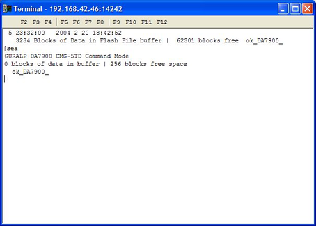
Check that there is two-way communication with the digitiser by pressing Enter. The digitiser should reply with ok on a new line. Type re-boot to reinitialize the digitiser, and confirm with y. As it is restarting, the digitiser will report its status over the terminal connection, followed by a maintenance menu:
I/OPort =$42 : RTModule no I2C ACK @ $78 MPE ARM ANS ROM PowerForth v6.30
ARM Serial BootStrap v1.100, 11 August 2003
Copyright (c) 2002-3 GSL, EDSL & MicroProcessor Engineering Ltd.
Port 0 38400 baud Port 1 38400 baud Port 2 38400 baud
Guralp Systems Ltd - ARM-BOOT v2.0 mgs 27/04/11 (Build 13)
System Code versions loaded :-
Current 0108:0000 Guralp Systems Ltd - DM+FW v.106 mgs 05/03/12 (Build 57d)
Previous 0110:0000 Guralp Systems Ltd - DM+FW v.106 mgs 05/03/12 (Build 57d)
Backup 0118:0000 Guralp Systems Ltd - DM+FW v.106 mgs 05/03/12 (Build 57d)
DSP Code :
0106:0000 dsp1090.bin Default
0107:0000 dsp1090.bin
Command keys:
C - set real time Clock (2013 11 13 17:17:55 )
I - view/upload InfoBlock
F - run the Forth monitor
S - update System program
O - select Other system program
B - update Boot program
D - update DSP code
T - Toggle default DSP code
Q - Quit maintenance system
5 seconds to auto-start Enter command:
If you do not press a key in the next five seconds, the digitiser will start up normally. The digitiser has three firmware components, which can be updated separately: the system program, the DSP code and the boot loader.
7.2.3.1 Loading a new system program
To update the system firmware, press S at the maintenance menu. The digitiser will then request a transfer using the Xmodem protocol. If you are using Scream!, a file browser window will appear automatically.
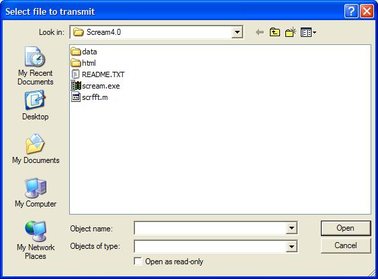
Navigate through the directories on your computer and select the file to be uploaded, or type in its full path and file name and click  .
.
Whilst the file is loading, a progress window will be displayed. Depending on the speed of the link, it may take up to 20 minutes to transfer the firmware. Once the file is fully transferred, the digitiser will return to the maintenance menu.
7.2.3.2 Loading new DSP code
Press D at the maintenance menu. The digitiser will reply with
Enter 0/1 to select DSP code to update
Select which of the two DSP code slots you want to overwrite, and press ENTER. The default is always 0.
Enter Filename/date – upto 31 characters
You can enter a descriptive string for the DSP code here. The digitiser will print this string at every boot-up, to remind you which version of the DSP code you are using. When you press ENTER, the digitiser will then request a transfer using the Xmodem protocol, as described above.
7.2.3.3 Loading a new boot loader
Press B at the maintenance menu to update the boot-loader. The digitiser will then request a transfer using the Xmodem protocol, as described above. When you are returned to the maintenance menu, press Q or wait 30 seconds for the system to restart.