Chapter 4. External Connectors and Controls.
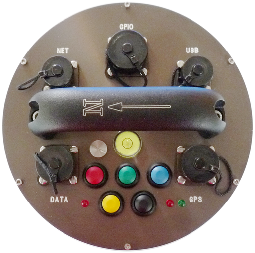
On the top of the instrument, you will find:
An Ethernet connector, labelled NET;
A general purpose input/output connector, labelled GPIO;
A universal serial bus connector, labelled USB;
The handle, with an arrow indicating “North”;
A bubble-level;
A “breather” screw, to allow the instrument to be assembled without a build-up of pressure internally.
A power and data connector, labelled DATA;
A GPS receiver connector, labelled GPS;
Five coloured push-buttons (described below);
A red LED (next to the yellow push-button) to indicate when data are being flushed to storage (described below); and
Two LEDs, one red, one green, next to the black push-button, to indicate the progress of locking, unlocking and centring operations.
The five connectors, NET, GPIO, USB, DATA and GPS, are connected internally to the embedded acquisition module and are described in MAN-EAM-0003.
The use of the “North” indication and the bubble level are described in MAN-C3E-0001.
The use of the push-buttons and LEDs are described in the following section.
4.1 Mass Control
The sensors' masses can be locked, unlocked and centred using the digitiser's command line, the EAM's command line or the web interface, Scream! software or the push-buttons on the top of the instrument. This section describes how to use the push buttons.
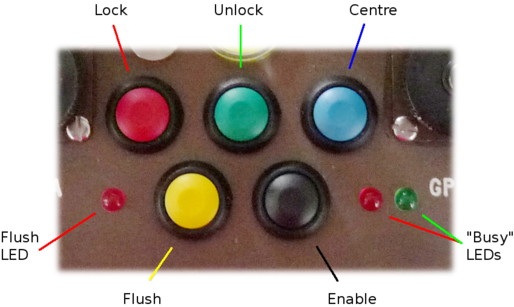
The two LEDs, on the right in the illustration above, provide an indication of the instruments status.
4.1.1 Unlock
To initiate the unlock function, hold down the green unlock button, then press the black enable button and release both after approximately 10 seconds. The internal processor will now perform the task of unlocking the sensor. There are several stages to this and the green LED shows the progress. If an error is encountered during the unlock process, the red LED will flash at the end of the operation. The precise pattern of flashing indicates the fault encountered. Details of LED states can be found in section 4.2.
4.1.2 Centre
To initiate the centre function, hold down the blue centre button, then press the black enable button and release both after approximately 10 seconds. The internal processor will now perform the task of centring the sensor. The green LED flashes during the centre process and then stays on once the centre is successful. If an error is encountered during the centring process, the red LED will illuminate at the end of the operation. The precise pattern of flashing indicates the fault encountered. Details of LED states can be found in section 4.2 on page 9.
4.1.3 Lock
To initiate the lock function, hold down the red lock button, then press the black enable button and release both after approximately 10 seconds. The internal processor will now perform the task of locking the sensor. There are several stages to this and the green LED shows the progress. If an error is encountered during the locking process, the red LED will illuminate at the end of the operation. The precise pattern of flashing indicates the fault encountered. Details of LED states can be found in section 4.2.
4.1.4 Auto Lock
The sensor has an automatic lock feature to ensure that the sensor is always locked when transported. If power is removed from the sensor for more than thirty seconds, an internal NiMH battery provides enough energy to initiate an automatic locking sequence.
Caution: If the sensor has been left standing powered off for expended periods of time (>3months) the sensor should be left powered for at least 48 hours before deployment to ensure that the internal battery is charged. Failure to do this may result in the auto lock function failing and damage to the sensor.
The auto-lock feature is enabled at the factory but can be disabled if desired.
To disable or re-enable the auto lock function, hold down both the blue centre and green unlock button, then press the black enable button until the red LED illuminates continuously. This sequence toggles the sensor between auto-lock enabled and disabled. Both busy LEDs blink together continuously to indicated the sensors' mode. The sensor should not be in a fault state prior to enabling this function. Details of LED states can be found in section 4.2.
4.1.5 Auto Centre
The instrument has an automatic centre function that will centre the sensor masses if their position exceeds a set threshold.
To enable and disable the auto centre function, hold down both the blue centre and the red lock buttons, then press the black enable button until the red LED illuminates continuously. This sequence toggles the sensor between auto-centre enabled and disabled. Both busy LEDs blink together continuously to indicated the sensors' mode. The sensor should not be in a fault state prior to enabling this function. Details of LED states can be found in section 4.2.
When Auto centre is enabled the sensor will initiate a centre operation if the mass position of any component exceeds the threshold continuously, for a set Delay period.
The default threshold is set to +/-1000 counts which is ±50% full scale. The delay period is set to 10 which equates to around 10 minutes.
4.2 Busy LEDs
The busy LEDs show the various states of the instrument. To do this they illuminate and flash in different sequences. The status LED sequence is based on 8 time segments that are repeated Either LED can be on or off during each time segment. The table below explains the LED states. A series of symbols are used to show when the LED is on or off.
LED sequence | Description of status |
Red: | Sensor is locked or powered off and no automatic functions are selected. |
Red: | Only auto-centre is enabled. |
Red: | Only auto-lock is enabled. |
Red: | Both auto-lock and auto-centre are enabled. |
Red: | Sensor is centred: auto-lock and auto-centre are both disabled. |
Red: | Sensor is centred and only auto-centre is enabled. |
Red: | Sensor is centred and only auto-lock is enabled. |
Red: | Sensor is centred and both auto-lock and auto-centre are enabled. |
Red: | Sensor is locking. |
Red: | Sensor is unlocking |
Red: | Sensor is centring |
Red: | Power failure waiting for auto-lock delay to time out (alternating red/green flashes). |
Red: | Catastrophic failure: the sensor has a fault that has made it impossible to complete the last operation. |
Red: | Locking system limit switch fault. |
Red: | Horizontal tilt base limit. This could be a result of a poorly levelled sensor. |
Red: | The current operation timed out. This could indicate a fault or, in the case of centring, the sensor may need to be re-centred. |
Here the symbol indicates that the led is off during a time segment and the symbol or indicates that the red or green LED is on. So, for example, the sequence of symbols indicates that the green LED is off for a long period of time (5 segments) then flashes twice.