Chapter 3. First encounters
3.1 Unpacking
The 3ESPCD seismometer is delivered in a single transportation case. The packaging is specifically designed for the instrument and should be reused whenever you need to transport it. Please note any damage to the packaging when you receive the equipment, and unpack on a safe, clean surface. The package contains the instrument and (almost always) the standard accessory kit, which contains:
the breakout box (which provides separate connections for the signal, control and power lines);
a Güralp GPS receiver unit with mounting rod;
a waterproof IEEE.1394 (FireWire) cable;
a 15 metre GPS cable, with six-pin bayonet connectors at both ends;
a power supply cable, with bare wires at one end and a ten-pin bayonet socket at the other;
a serial data cable, with a standard nine-pin D connector at one end and a ten-pin bayonet plug at the other; and
a calibration and installation sheet.
If you have ordered an instrument with the wired Ethernet option, the accessory kit will contain all of the above and, in addition, an Ethernet cable.
If you have ordered an instrument with the wireless Ethernet option, the accessory kit will contain all of the above and, in addition, an Ethernet cable, a Wi-Fi. antenna and a network diagnostics cable.
Assuming all the parts are present, stand the seismometer in the centre of a bench and identify its external features:
a handle with an engraved North indication,
a nineteen-way bayonet plug for data, power and GPS signals;
a six-way bayonet plug for the FireWire interface;
if fitted, a six-way bayonet plug for the Ethernet interface;
if fitted, an antenna connector for the Wi-Fi interface;
a bubble level,
an air vent port,
three feet (two adjustable, and one fixed), and
two accurate orientation pins (one brass and one steel).
3.2 Serial number
The sensor's serial number can be found on the label fixed to the top lid of the sensor. You should quote this serial number if you need assistance from Güralp Systems.
3.3 Handling notes
The 3ESPCD is a sensitive instrument, and is easily damaged if mishandled. If you are at all unsure about the handling or installation of the device, you should contact Güralp Systems for assistance.
Avoid bumping or jolting any part of the sensor when handling or unpacking.
Do not kink or walk on the data cable (especially on rough surfaces such as gravel), nor allow it to bear the weight of the sensor.
Do not connect the instrument to power sources except where instructed.
Do not ground any of the signal lines from the sensor.
Avoid moving the instrument whilst the masses are unlocked.
3.4 Connections
The instrument has the following connectors:
The main 19-way connector is for the break-out box, which accepts a power input, outputs serial data to your PC or data module and also accepts timing signals from an attached GPS receiver;
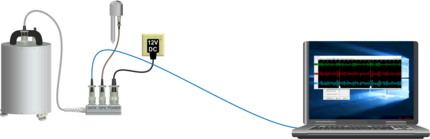
The FIREWIRE connector can be attached to a Güralp IEEE.1394 (FireWire) hard disk using the cable provided;
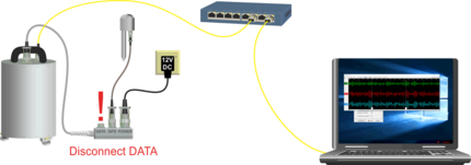
Optional - The Ethernet connector provides a 10/100BASE-T connection to a built-in Lantronix serial-to-Ethernet converter;
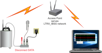
Optional - The Wi-Fi. antenna connector can be used with the supplied stub antenna or, via a cable, with a remote or high-gain Wi-Fi. antenna to provide wireless network connectivity, via a built-in Lantronix serial-to-WiFi converter.
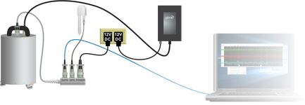
3.5 Power supply
The sensor requires a supply of 10 to 28 V DC power, which it obtains via the Break-out Box. The supplied power cable is supplied with bare ends: we recommend that you terminate it with a polarised connector suitable for your application. A bench power supply or a lead-acid battery is suitable for testing. (Using a 12 V, 25 Ah sealed, heavy-duty, deep-discharge, lead-acid battery, you should expect the instrument to operate for around a week without recharging.)
The 3ESPCD draws a nominal current of 140 mA from a 12 V supply (≈1.6 W) when in use. During locking and unlocking of the sensor masses, this current rises briefly to 750 mA. It is recommended that you carry a spare 12 V battery when visiting a battery-powered installation for maintenance, in case the sensor needs to be moved and the on-site batteries no longer have sufficient charge to perform the locking procedure.
Caution: Observe the correct polarity when connecting the power supply. The red lead must be connected to the positive terminal, typically labelled ‘+’, and the black lead must be connected to the negative terminal, typically labelled ‘-’. An incorrect connection risks destroying both the instrument and the power supply.