Chapter 7. Appendices
7.1 Appendix A - Connector pin-outs
7.1.1 Sensor and control unit output
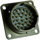
This is a standard 26-pin “mil-spec” plug, conforming to MIL‑DTL‑26482 (formerly MIL‑C‑26482). A typical part-number is ***‑16‑26P where the '***' is defined by the manufacturer. Suitable mating connectors have part-numbers like ***‑16‑26S. |
|
The 26‑pin connectors on the breakout box have identical pin-outs.
Pin | Function | Pin | Function |
A | Velocity +ve, vertical channel | P | Calibration signal (all channels) |
B | Velocity –ve, vertical channel | R | Calibration enable, Z channel |
C | Velocity +ve, N/S channel | S | Calibration enable, N/S channel |
D | Velocity –ve, N/S channel | T | Calibration enable, E/W channel |
E | Velocity +ve, E/W channel | U | Centre |
F | Velocity –ve, E/W channel | V | not connected |
G | Mass position, vertical channel | W | Unlock |
H | not connected | X | Lock |
J | Mass position, N/S channel | Y | Logic ground |
K | BUSY LED | Z | not connected |
L | Mass position, E/W channel | a | not connected |
M | Power –ve (split supply option) | b | Power ground |
N | Analogue ground | c | Power +ve |
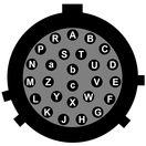
| Wiring details for the compatible socket, ***‑16‑26S, as seen from the cable end (i.e. when assembling). |
7.1.2 Breakout box DC power connector
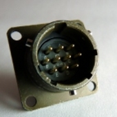
This is a standard 10-pin “mil-spec” plug, conforming to MIL‑DTL‑26482 (formerly MIL‑C‑26482). A typical part-number is ***‑12‑10P where the '***' is defined by the manufacturer. Suitable mating connectors have part-numbers like ***‑12‑10S. |
|
Pin | Function |
A | 0 V |
B | +12 V DC supply |
C | not connected |
D | not connected |
E | not connected |
F | not connected |
G | not connected |
H | –12 V DC supply (not used in sensors with internal DC-DC converters) |
J | not connected |
K | not connected |
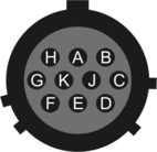
| Wiring details for the compatible socket, ***‑12‑10S, as seen from the cable end (i.e. when assembling). |
7.2 Appendix B - Specifications
Parameter | Specification |
Hybrid sensors | 0.1 – 50 Hz |
Velocity output bandwidth | |
High pass filter output flat to acceleration | 0.01 Hz – spec* |
High pass filter output flat to velocity | spec – 50 Hz* |
Mass position output | DC – 0.1 Hz |
Velocity sensitivity | 1400 V/m/s |
Acceleration sensitivity | 2000 V/m/s2 |
Velocity sensors | |
Velocity output bandwidth | spec – 50 Hz* |
Mass position output | DC – spec Hz* |
Velocity sensitivity | 2 × 750 V/m/s |
Mass position sensitivity | 1000 V/m/s2 |
Mass locking and unlocking | manual; optional remote operation |
Mass centring | automatic, MPU controlled |
Sensors | 3 orthogonal, each 0.180 kg |
Lowest spurious resonance | above 140 Hz |
Total weight | 11 kg |
Sensor transducer type | capacitive displacement |
Feedback transducer type | magnet/coil |
Connector | pressure tight |
Temperature range with masses locked | –35 to +75 °C |
Operational temperature range | –20 to +65 °C** |
Input voltage | 10 – 36 V |
Current at 12 V DC | 75 mA† |
Current at 12 V DC during calibration | 100 mA† |
Current at 12 V DC during centring | 330 mA† |
Current at 12 V DC during locking and unlocking | 490 mA† |
*spec refers to the quoted frequency response value, e.g., for a “30 s” sensor, the value of spec would be 30 s = 0.033 Hz.
**Temperatures below –20 °C may be accommodated with additional care. Please consult Güralp Systems for advice.
†Because centring, locking, and unlocking consume varying amounts of power, it is recommended that you use a power supply capable of delivering 1 A at 12 V.
7.3 Appendix C - Revision history
2000-04-28 | A | New document |
2006-02-21 | C | Updates; added revision history |
2006-11-15 | D | Redrawn diagrams |
2011-03-18 | E | Changes to vault procedures, formatting updates |
2011-08-23 | F | Corrections to connector pin-out |
2016-02-18 | G | Corrections to connector pin-out |