Chapter 5. Appendices
5.1 Appendix A - Configuration
The Lantronix WiPort NR networking module has a serial-accessible configuration system which can be used to configure them. For full details, refer to: http://www.lantronix.com/pdf/WiPort-NR_UG.pdf
5.1.1 Accessing the configuration menu via the serial Interface
Access to the configuration menu over the serial interface can be obtained using any serial terminal emulator (see Appendix B on page 11). If used in conjunction with a Güralp EAM, Güralp Affinity or Güralp DM24SxEAM, the built-in minicom emulator can be used for this purpose.
The procedure for connecting to the device is:
Disconnect the power supply.
Connect a serial cable between the PC and the SERIAL 1 connector.
Open a terminal connection as described in Appendix B on page 11. Use 9600 baud (even if the port was earlier configured for another baud rate).
Hold down the
 key while applying power to the acquisition module.
After a few seconds, a banner will appear, showing the MAC address of the network interface, along with software and library version information. Press the Enter key to access the set-up menu. If you do not press a key, the system will proceed to boot normally.
5.1.2 Configuring the serial ports
Once you have access to the networking module's configuration menu, you can configure it with its proper settings.
During the configuration process, you are prompted, in turn, for every value in the current section. If you are unsure at any point, pressing the Enter key will retain the current value. Please note that many values need to be entered using special codes. These are all documented in the relevant Lantronix manuals.
From the main menu:
Each serial port is configured individually. To configure either press 1 (SERIAL 1) or 2 (SERIAL 2).
Set the Baud Rate as desired.
The remaining settings can be left at their default values, which is done by pressing Enter at each prompt until you are returned to the main menu.
When you have finished setting up the module, apply the new settings by selecting option 9 Save and Exit. The module will re-boot with the new settings in effect.
5.1.3 Configuring the Ethernet port
To configure the Ethernet port
If DHCP is not being used to assign IP addresses, enter the required address manually. The IP address must be set to a unique value in the network. Enter each octet and press Enter to move to the next octet. The current value is displayed in parentheses. If you do wish to use DHCP, enter 0 at each prompt (an IP address of 0.0.0.0 is used to select DHCP operation).
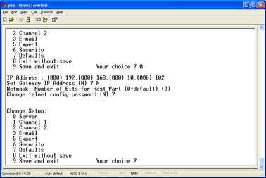
If the system is to be connected to a routed network, enter the address of the default gateway in the same manner.
At the netmask prompt, enter 0 if you are using normal (classful) internet addressing. If you have a non-standard or classless addressing scheme, enter the number of bits of the IP address to be used for network identification. Note that this is not the standard way of specifying netmasks; it is more akin to the /n modifier used in CIDR address specification.
When you have finished setting up the module, apply the new settings by selecting option 9 Save and Exit. The module will re-boot with the new settings in effect.
5.2 Appendix B - Using terminal emulators
There are a number of terminal emulator programs that you can use to access the serial ports of the system and networking interfaces. Three of these are detailed below.
5.2.1 Hyperterminal, as provided with Windows XP.
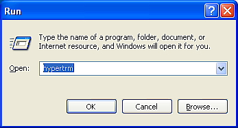
Click on Start and then Run.
Enter 'hypertrm' and click on OK.
The program will ask you for a name for the connection:
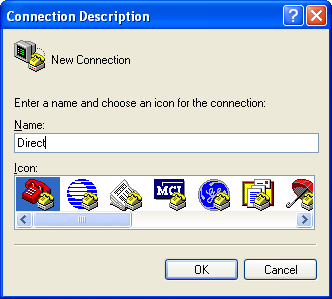
Enter any suitable name, then click OK.
You will then be prompted to enter COM port and modem details:
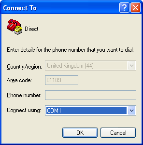
The Country/region, Area code and Phone number fields can be ignored: they are only used when working with modem connections. Select the name of the correct COM port from the Connect using drop-down menu, then click OK.
Enter the port configuration settings:
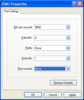
Ensure the following parameters are set:
Bits per second: 9600
Data bits: 8
Parity: None
Stop bits: 1
Flow control: None
Click on OK and the program will then connect provide you with a terminal emulator screen, from which you can access the command line of your system.
5.2.2 Using Hyperterminal with Windows Vista or Windows 7.
HyperTerminal is not provided with the Windows Vista or Windows 7 operating systems but the necessary files can be copied from the i386 directory of the Windows XP CD if you have one available. The two files you will need are:
hypertrm.dll
hypertrm.exe.
If you do not have a Windows XP disc the files can be downloaded from: www.mediafire.com
To use Hyperterminal with Windows Vista or Windows 7:
Copy the two files into your windows/system32 directory.
To access HyperTerminal, use Windows+R on your keyboard. Enter 'hypertrm' and click on OK.
If Windows open a security warning window click on Run. You may also be asked if you wish to use HyperTerminal as a the default terminal window.
Now follow the instructions given in section 5.2.1, above.
5.2.3 Using PuTTY.
PuTTY is a free terminal package for windows which is useful if HyperTerminal is not available. It can be downloaded from www.chiark.greenend.org.uk. The easiest package to use is the 'windows installer'. Install PuTTY by following the on-screen instructions.
Start PuTTY by clicking on the desktop icon or Start-menu entry
Click on Serial at the bottom of the category menu on the left:
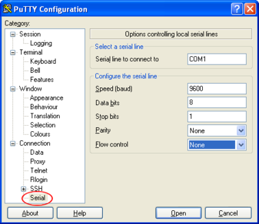
Select a serial line to connect to. This is usually COM1.
Configure the serial line with the following settings:
Speed (baud): 9600
Data bits: 8
Stop bits: 1
Parity: None
Flow control: None
Click on Session in the main menu on the left.
In the right hand part of the window use the radio buttons to select the Serial Connection type. Check the Serial line and Speed fields are correct:
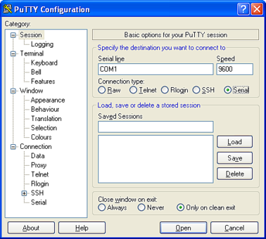
To save the settings enter a suitable session name in the Saved Sessions field then click Save.
The next time you start PuTTY, your saved session will appear in the list and you can simply double-click it to open a new session with the same settings.
Click the Open button to start the terminal emulator.
5.2.4 Using minicom
The minicom terminal emulator is installed by default in many Linux distributions and is included in the Platinum firmware of Güralp EAMs, Affinity units or DM24SxEAMs.
Minicom is window-based. To pop up a window with the function you want, hold the  key while typing
  (from now on, we will use
  +
+ to denote this), and then a key to select the function (a-z or A-Z). By pressing
  +
+ first and then
  , a help screen comes up with a short summary of all commands.
For every menu the following keys can be used:
Key | Action |
| UP |
| DOWN |
| LEFT |
| RIGHT |
| CHOOSE |
| CANCEL |
 or
or 
 or
or 
 or
or 
 or
or 


The screen is divided into two portions: the upper 24 lines are the terminal-emulator screen. In this window, ANSI or VT100 escape sequences are interpreted. If there is a line left at the bottom, a status line is placed there. If this is not possible the status line will be showed every time you press  +
+ . On terminals that have a special status line, it will be used if the termcap information is complete and the -k flag has been given. Possible commands are listed next, in alphabetical order.
Key | Action |
| Pressing |
| Toggle 'Add Linefeed' on/off. If it is on, a linefeed is added before every carriage return displayed on the screen. |
| Gives you a scroll back buffer. You can scroll up with |
| Clears the screen. |
| Toggle local echo on and off. |
| A break signal is sent. |
| Toggle the type of escape sequence that the cursor keys send between normal and applications mode. (See also the comment about the status line below). |
| Jump to a shell. On return, the whole screen will be redrawn. |
| Clears the screen, runs kermit and redraws the screen upon return. |
| Turn Capture file on off. If turned on, all output sent to the screen will be captured in the file too. |
| Configure minicom. Puts you in the configuration menu. |
| Communication Parameters. Allows you to change the bps rate, parity and number of bits. |
| Exit minicom without resetting the modem. If macros changed and were not saved, you will have a chance to do so. |
| Receive files. Choose from various protocols (external). If you have the filename selection window and the prompt for download directory enabled, you'll get a selection window for choosing the directory for downloading. Otherwise the download directory defined in the Filenames and paths menu will be used. |
| Send files. Choose the protocol like you do with the receive command. If you don't have the file-name selection window enabled (in the File transfer protocols menu), you'll just have to write the file-name(s) in a dialog window. If you have the selection window enabled, a window will pop up showing the file-names in your upload directory. You can tag and un-tag file-names by pressing |
| Choose Terminal emulation: Ansi(colour) or vt100. You can also change the backspace key here, turn the status line on or off, and define delay (in milliseconds) after each newline if you need that. |
| Toggle line-wrap on/off. |
| Exit minicom, reset modem. If macros changed and were not saved, you will have a chance to do so. |
| Paste a file. Reads a file and sends its contents just as if it would be typed in. |
| Pop up the help screen. |
 +
+ +
+ +
+ +
+
 , down with
  , a page up with
  and, if you have them, the


 and
and 
 keys can also be used. You can search for text in the buffer with
  (case-sensitive) or
  +
+ will find the next occurrence of the string.
  will enter citation mode. A text cursor appears and you specify the start line by hitting
  key. Then scroll back mode will finish and the contents with prefix '>' will be sent.


 , and move the cursor up and down with
  twice. Finally, send the files by pressing
  or quit by pressing


5.3 Appendix C - Lantronix WiPort NR Device Manager
The internal WiPort NR device can be accessed using a web-interface. For full details, refer to: http://www.lantronix.com/pdf/WiPort-NR_UG.pdf
If this is not possible, configuration of the interface can be carried out using the Lantronix' DeviceInstaller utility for Microsoft Windows, using a DHCP server or the via the serial port. You will need a PC with a network interface installed or an RS232 connector.
Note: Refer to Appendix D on page 22 for information on connector pin-outs.
Download and install the DeviceInstaller utility from the Lantronix Web site at www.lantronix.com.
DeviceInstaller requires the Microsoft .NET framework to be installed. If you do not have this already, it can be downloaded from: www.microsoft.com.
Note that DeviceInstaller will not work through routers or across the Internet. All the devices need to be on the same network segment as the PC.
Find out the MAC address of the network interface. This should be printed on a label on the case.
Connect the 6-pin Ethernet port to the the PC's network interface either using a crossover Ethernet cable or through a network hub. Note that using a hub, you can connect several systems to the same PC and configure them all at the same time.
Use the power cable to connect the 4-pin power connector to a fused 10 – 28 V power source. A 12V DC power supply is recommended.
Run DeviceInstaller.
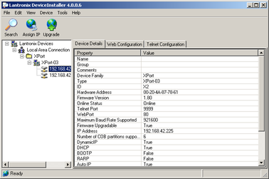
DeviceInstaller's main window has two panels, a tree on the left (with Lantronix Devices at the top) and a table on the right.
The program will automatically look for Lantronix devices on all of your computer's network interfaces. If necessary, you can narrow the selection by clicking on an entry in the tree on the left. If the program does not list the device, press F5 or use Device > Search from the menu system.
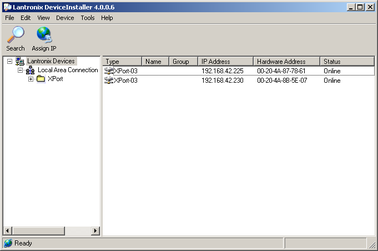
A WiPort NR entry should appear in the table on the right, denoting that a device has been detected.
If more than one WiPort NR entry appears, DeviceInstaller has detected several devices.
For every detected device, the program shows the Hardware Address (i.e. the MAC address) and the IP address it is currently using. If you are using a wireless router with a DHCP server, or an access point connected to a network with a DHCP server, the device will use DHCP to assign it an address. Otherwise, a random address will be chosen automatically.
Note: Automatic random addresses all begin with 169.254. The system will choose a different one every time it is power cycled or rebooted.
The address of the system may be shown in red with the status Unreachable. If this happens, the system and PC cannot communicate because they are not on the same subnet. Click Assign IP to start the IP configuration wizard. Follow the instructions in the wizard to set the IP address, or configure DHCP if you are using a DHCP server. When you have finished, press F5 or use Device > Search from the menu system to find the sensor with its new IP address.
Note: The IP address of the system must have be on the same subnet as the computer you want to connect to. The LAN setting on the DeviceInstaller device tree identifies the IP address of your computer. The first three number groups typically need to be the same on all devices (digitisers and computer).
If you want to configure the system to use a static IP address, use the Assign IP wizard as above and click Search again.
Double-click on the entry which corresponds to the system you want to configure. The right-hand panel will change to show the current properties of the device.
Switch to the Web Configuration tab and click Go to open the Web configuration interface.
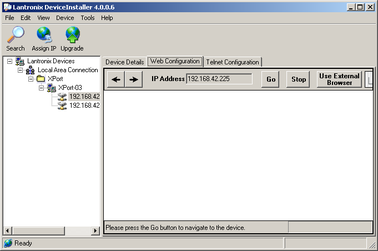
You can also click Use External Browser to use your own Web browser to configure the system.
5.4 Appendix D - Connector pin-outs
5.4.1 ETHERNET
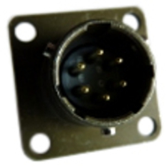
This is a standard 6-pin “mil-spec” plug, conforming to MIL-DTL-26482 (formerly MIL-C-26482). A typical part-number is 02E-10-06P although the initial “02E” varies with manufacturer. Suitable mating connectors have part-numbers like ***-10-06S and are available from Amphenol, ITT Cannon and other manufacturers. |
|
Pin | Function |
A | Power input, 0V |
B | Data transmit +ve (RJ45 pin 1) |
C | Data receive +ve (RJ45 pin 3) |
D | Power input, 10V–28V DC |
E | Data receive –ve (RJ45 pin 6) |
F | Data transmit –ve (RJ45 pin 2) |
| Wiring details for the compatible socket, ***-10-06S, as seen from the cable end (i.e. during assembly). |

5.4.2 SERIAL 1 and SERIAL 2
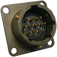
This is a standard 10-pin “mil-spec” plug, conforming to MIL-DTL-26482 (formerly MIL-C-26482). A typical part-number is 02E-12-10P although the initial “02E” varies with manufacturer. Suitable mating connectors have part-numbers like ***-12-10S and are available from Amphenol, ITT Cannon and other manufacturers. |
|

Pin | Function |
A | Power input/output, 0V |
B | Power input/output, 10V–28V DC |
C | not connected |
D | not connected |
E | not connected |
F | not connected |
G | RS232 ground |
H | not connected |
J | RS232 receive |
K | RS232 transmit |
| Wiring details for the compatible socket, ***-12-10S, as seen from the cable end (i.e. during assembly). |

5.4.3 POWER
This is a standard 10-pin “mil-spec” plug, conforming to MIL-DTL-26482 (formerly MIL-C-26482). A typical part-number is 02E-12-10P although the initial “02E” varies with manufacturer. Suitable mating connectors have part-numbers like ***-12-10S and are available from Amphenol, ITT Cannon and other manufacturers. |
|
Pin | Function |
A | Power input/output, 0V |
B | Power input/output, 10V–28V DC |
C | not connected |
D | not connected |
E | not connected |
F | not connected |
G | not connected |
H | not connected |
J | not connected |
K | not connected |
| Wiring details for the compatible socket, ***-12-10S, as seen from the cable end (i.e. during assembly). |

5.5 Appendix E - Revision history
18 Sep 2012 | A | New document |
6 Nov 2013 | B | Revised power distribution arrangements. |
18 May 2016 | New branding and added Affinity examples |