Chapter 3. The new behaviour
This chapter describes the operational behaviour of 3TB borehole instruments when running the new SoH firmware.
3.1 The BUSY LED
Güralp hand-held controllers and break-out boxes are equipped with an LED labelled "BUSY".
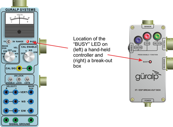
This LED provides feedback about the current state of the SoH processor.
The signal which drives the LED can also be monitored by a connected digitiser. This signal appears on pin W of the instrument's 32-way connector but it is more usually encountered on pin K of the 26-way connector on the break-out box's RECORDER connector. This is a TTL-level signal - i.e. +5 V when active, and 0 V otherwise - referenced to digital ground, which is found on pin f of the instrument's 32-way connector or pin Y of the break-out box's RECORDER connector.
3.1.1 Interpretation
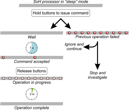
The BUSY LED has four modes to indicate the state of operation of the SoH.
Not illuminated or flashing

This means that the SoH is not currently active. The SoH processor enters a low-power "sleep" mode after each operation. The LED is never illuminated during sleep mode. (The SoH can be woken by briefly pressing the "Enable" button plus any control button or by briefly activating any control line.)
Slow, bright flashing

A slow, bright flash indicates that the SoH has received and accepted a command. It is the SoH's response to a button press or logic input with a duration of more than six seconds. The six-second guard period is to prevent false triggering caused by transient interference. The flashing will continue for a minimum of two seconds. After this:
If the SoH is acting on the horizontal components, the LED will start a dim, fast flash, as described below.
If the SoH is acting on the vertical component, the slow, bright flashing will continue for as long as the vertical component is busy.
Fast, dim flashing

A fast, dim flash indicates that the SoH is busy carrying out an operation. It follows the slow, bright flashing described above. The fast, dim flashing will continue for the duration of the operation.
Fast, bright flashing

A fast, bright flash indicates that the last SoH operation has failed.
Caution: Note that fast, bright flashing is not visible unless the SoH has been woken. This is because the SoH enters a low-power sleep mode after completing an operation. The SoH can be woken by a brief press of the "Enable" button plus any of the command buttons or by a brief activation of any control line.
The general sequence of events for a mass-control operation is thus:
Each mass control operation is discussed in detail in the following sections.
3.2 Locking the sensor
3.2.1 Initiating
To initiate a locking operation, press and hold both the ENABLE and the LOCK buttons/switches simultaneously until the LED displays a slow, bright flash. This will take around seven seconds. Release the buttons/switches. The system should now start locking and the BUSY LED will display a fast, dim flash while the operation is in progress.
Caution: If the BUSY LED starts fast, bright flashing immediately after pressing the button, the instrument is in a fault state. See "Detecting a Fault" in section 3.5.
Note: The locking process will take between one and three minutes. The BUSY LED will show a fast, dim flash throughout the operation.
When the slow, dim flashing stops, the instrument should be locked but it is important to verify this before moving the instrument. Verification is described in the following section.
3.2.2 Verification
To verify that the instrument is locked, press and hold the enable and lock buttons/switches simultaneously for at least six seconds. If the LED displays a fault state (fast, bright flashing), ignore this.
If the instrument is locked, the BUSY LED will flash slowly for a few seconds followed by a dim faster flash and then stop. This process should take approximately ten seconds.
If, for any reason, the sensor was not locked, the BUSY LED will flash for longer than ten seconds. If this is the case, repeat the verification process until the busy light only flashes for around 10 seconds.
When the sensor is locked, all masses will have been physically moved to their end-stops. The mass position outputs, however, will all be reported as zero because the SoH turns off the analogue electronics. This is in order to conserve power.
Caution: The instrument must be in an upright position before locking. It should never be operated on its side.
3.3 Unlocking the sensor
3.3.1 Initiation
To initiate an unlocking operation, press and hold both the ENABLE and the UNLOCK buttons/switches simultaneously until the LED displays a slow, bright flash. This will take around seven seconds. Release the buttons/switches. The system should now start unlocking and the BUSY LED will display a fast, dim flash while the operation is in progress.
Caution: If the BUSY LED starts fast, bright flashing immediately after pressing the button, the instrument is in a fault state. See "Detecting a Fault" in section 3.5. You should not attempt to unlock an instrument which is in a fault state. It should only be unlocked after a successful lock operation has been verified, as described in section 3.2.2.
The unlocking process can take up to six minutes, depending on the angle of the sensor. You can monitor the state of the mass positions during the operation by using the meter on a hand-held control unit. The vertical mass is unlocked first, followed by the north/south mass and, finally, the east/west mass.
Note: Monitoring the mass position provides valuable feedback that the instrument is operating correctly and, with experience, any departures from the normal routine can be identified.
It should be noted that the instrument should only be unlocked if the instrument is in the upright position and the inclinometer control box has both meters in the green region.
Caution: The instrument must be in the upright position and both meters on the inclinometer control box must show readings in the green region before unlocking. It should never be unlocked under any other circumstances.
3.3.2 Verification
Successful unlocking can easily be verified by observing seismic waveforms on the main velocity outputs and near-zero values from the mass position outputs.
3.4 Centring the sensor.
3.4.1 Initiation
To initiate a centring (also called "nulling") operation, press and hold both the ENABLE and the CENTRE buttons/switches simultaneously until the LED displays a slow, bright flash. This will take around seven seconds. Release the buttons/switches. The system should now start centring and the BUSY LED will display a fast, dim flash while the operation is in progress.
Caution: If the BUSY LED starts fast, bright flashing immediately after pressing the button, the instrument is in a fault state. See "Detecting a Fault" in section 3.5.
The centring process can take up to five minutes depending on the angle of inclination of the sensor.
3.4.2 Verification
The mass position outputs can be monitored during the operation using the attached digitiser or the meters on a hand-held control unit.
3.5 Detecting a Fault
The SoH will declare a fault condition if one of the following situations exists:
The requested operation - Centre, Lock, or Unlock - has timed out;
The tilt range of any one of the sensor components has been exceeded.
In either of these cases, the SoH will rapidly flash the BUSY LED with bright pulses.
Note: The fault indication always refers to the previous operation, not the one being requested.
It is necessary to hold both ENABLE and any one of the function switches in order to observe the fault indication. This can be a brief press in order to avoid initiating another function, which requires a six-second press. The fault indication will appear immediately when the buttons are pressed and continue for approximately ten seconds after they have been released.
If you wish to initiate an operation while the SoH is indicating a fault condition, simply ignore the fault indication and continue to hold the switch for seven seconds until the slow, bright flash is observed.
Any component that has successfully unlocked will continue to respond to the centre command.
If the sensor is to be repositioned or recovered it must be locked first, before it is moved. Please also verify the lock state as mentioned above.
Caution: If the instrument is to be repositioned or recovered, it must first be locked, as described in section 3.2.1 and the lock verified, as described in section 3.2.2, before any attempt is made to move the instrument. Failure to observe this requirement can result in expensive damage.