Chapter 5. GPS adapter cable specification
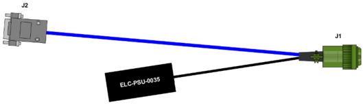
5.1 J1 – GPS Receiver connection
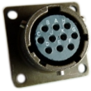
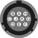
This is a standard 10-pin “mil-spec” socket, conforming to MIL-DTL-26482 (formerly MIL-C-26482). A typical part-number is 02E-12-10S although the initial “02E” varies with manufacturer. Suitable mating connectors have part-numbers like ***-12-10P and are available from Amphenol, ITT Cannon and others |
|
Pin | Function |
A | Power supply 0 V |
B | Power supply +24 V |
C | 1 pulse-per-second (PPS) signal from GPS |
D | not connected |
E | not connected |
F | not connected |
G | RS232 ground |
H | not connected |
J | RS232 TxD |
K | RS232 RxD (NMEA data from GPS receiver) |
| Wiring details for the compatible plug, ***-12-10P, as seen from the cable end (i.e. when assembling). |
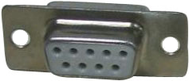
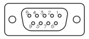
5.2 J2 – Connection to NAM Port A or Port B
This is a standard DE9F (TIA-574) sub-miniature (D-sub) socket, conforming to DIN 41652 and MIL-DTL-24308. They are very widely available, as are suitable mating connectors. |
|
Pin | Function |
1 | 1 pulse-per-second (PPS) signal from GPS |
2 | RS232 RxD (NMEA data from GPS receiver) |
3 | RS232 TxD |
4 | Not connected |
5 | RS232 ground |
6 | Not connected |
7 | Not connected |
8 | Not connected |
9 | Not connected |
| Wiring details for the compatible plug, DE9M, as seen from the cable end (i.e. during assembly). |
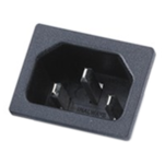
5.3 Integrated GPS power supply inlet
The integrated power supply unit accepts an AC input voltage of between 100 V and 240 V at 50 Hz or 60 Hz. The input supply should be capable of providing 1.7 A.
The power inlet is a standard C14 connector, conforming to IEC 60320-1. They are very widely available, as are suitable C13 mating connectors. No pin-out details are given here. It is recommended that commercially-available power cables with moulded connectors are used. |
|