Chapter 3. Emergency Locking
3.1 Equipment Required
You will require the following:
A clean environment in which to work, including suitable ESD equipment (dissipative surface, wristband, etc.);
A 2mm hexagonal driver;
A medium-sized, flat-bladed screw-driver;
A soldering iron; and
A permanent marker.
3.2 Sensor disassembly.
Caution: Seismometers and accelerometers contain extremely sensitive mechanical components. Only open the casing of an instrument in a clean environment and take precautions to prevent any ingress of dust into the body of the instrument.
Caution: The circuit boards contained within the instrument include components which can be damaged by electrostatic discharge. Always work on a properly grounded dissipative surface and wear a suitable grounded wristband. Ground yourself by touching an earthed conductor before handling any of the circuit boards.
To gain access to the sensor components, it is first necessary to remove the lid of the instrument, along with any associated electronics, and the outer sleeve.
The instrument lid is secured using a number of small screws located around the top, outside edge. The lid extends a short way down inside the cylindrical casing and two 'O'-rings provide sealing between the lid and the cylinder. The seal thus formed can make it difficult to remove the lid due to the differential pressure between the inside and the outside of the casing. A pressure-relief screw is provided for this reason.
Warning: For your own safety and that of the instrument, please read and understand all of the following procedure before commencing disassembly. If in any doubt, please contact Güralp technical support for advice.
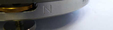
Locate the North indicator on the base of the instrument. This may be a stamped 'N' or a gold-coloured stud. If no such indication can be found, use a permanent marker to mark the position of the cylinder with respect to both the base and the lid:
Using the 2mm hexagonal driver, remove the screws around the top edge of the cylinder:
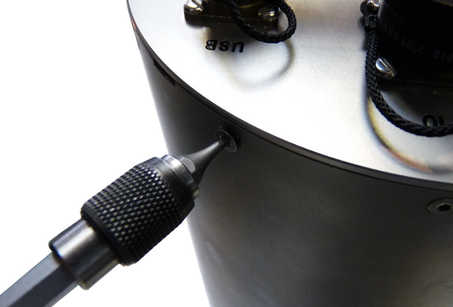
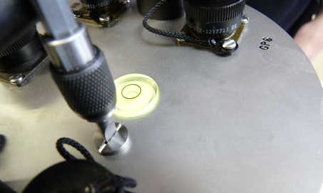
Using the flat-bladed screwdriver, remove the pressure relief screw from the top of the lid:
Warning: Instruments are assembled near sea level. If working at altitude, there may be a considerable pressure difference between the inside of the instrument and local atmospheric pressure. Ensure that the pressure-relief screw does not fly off when released. Failure to do so may cause injury.
Remove the lid from the instrument. It will, initially, be difficult to remove because of the 'O'-rings.
Caution: The force required will drop significantly when the 'O'-ring seals become clear of the the top of the cylinder. Take particular care that the lid does not “fly off” when this happens.
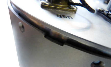
The electrical connections between the lid electronics and the rest of the instrument are via a 150mm ribbon cable so it is acceptable to rotate the lid slightly to ease it from its seal. Be careful not to rotate it too far - 10° or so in either direction is a safe limit. If the lid proves very hard to move, a flat-headed screw-driver can be inserted into the small slot formed by a cut-out in the top of the cylinder and used for leverage:
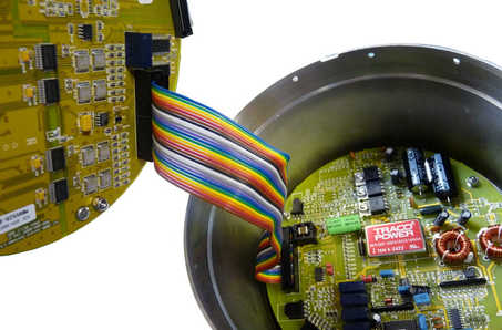
Lift the lid away from the cylinder and, wearing an anti-static wrist-band, disconnect (at either end) the ribbon cable connecting it to the lower electronics:
Using the 2mm hexagonal driver, remove the screws around the bottom edge of the cylinder and gently prise the cylinder away from the base. Take extreme care not to knock any of the sensor components.
Carefully lift the cylinder up and over the sensor, taking care not to catch any of the fine wires.
Different models from the 3-series instrument range have different sets of electronics fitted and different revisions have used slightly different mechanical arrangements so what you see at this stage may differ from the illustrations. Use common sense and proceed with care. If you are in any doubt, please consult Güralp Systems technical support for advice. It may be helpful for you to take photographs as you work - both for avoiding any doubt during reassembly and to aid in reporting problems, should you encounter any. Photographs also help GSL support staff in identifying the precise revision of instrument with which you are working.
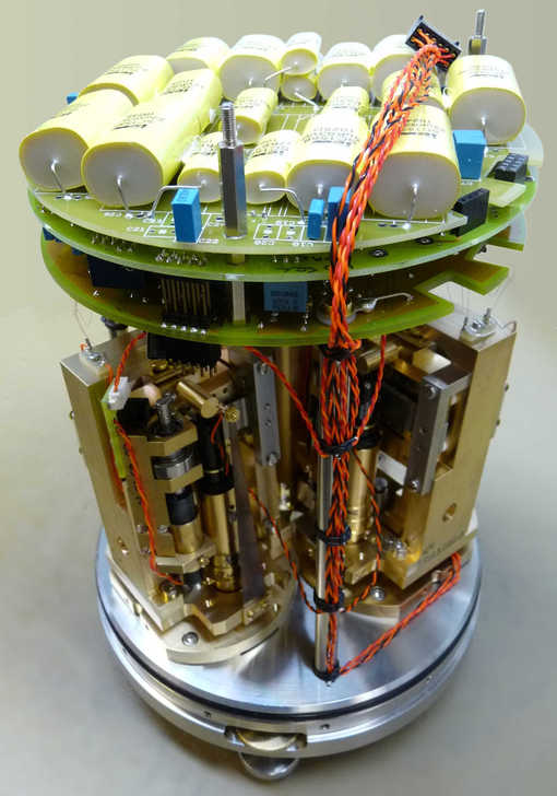
Identify the three component sensors: the vertical sensor is immediately obvious as its design differs significantly from the horizontals. The two horizontal sensors are usually hand-marked during assembly, as in the photo below: if not, the fine wires from the tops of the sensors can be traced to the feedback board, where the PCB's silk-screening will identify which is which. If all else fails, compare the axes of movement of the masses with the North indication on the base-plate.
3.3 Electrically driving the mass-lock motors
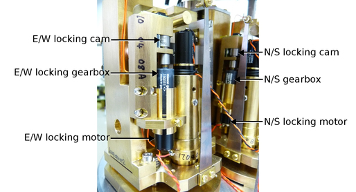
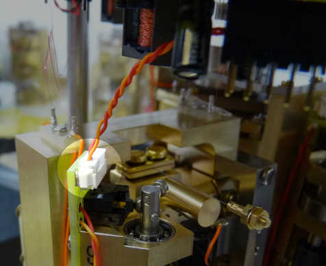
If it is impossible to lock the masses because of failure of the associated electronics, the mass lock motors can be driven directly in order to lock the masses. In normal use, the motors are electrically isolated by relays, so it is perfectly safe to connect a power supply to the motors without first having to disconnect them from the electronics. The picture below identifies the key parts on the horizontal sensors:
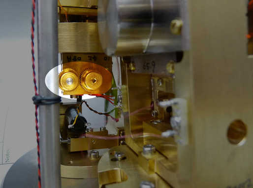
The key parts for the vertical sensor are identified in the picture below:
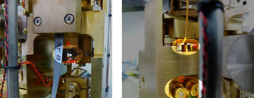
The motor is at 'A' in the left-hand picture. In the right-hand picture, B is the locking pin and C is the supplementary gear-train.
To drive the motors, apply 5V DC power directly to the wires where they are soldered to the motors and observe the operation of the locking mechanism. When the locking pin is fully extended, the mass will be clamped. This can be verified by gently attempting to move the mass. If any motion is observed, repeat with the polarity reversed to drive the motors in the opposite direction.
3.4 Manually driving the mass-locks
If the motors or gearboxes have failed, it may not be possible to electrically lock the masses. In this case, the mechanisms will have to be manipulated manually.
Access to the North/South sensor component is severely restricted by the location of the East/West sensor component. It is advisable to first lock the East/West sensor component and then physically remove it before addressing the North/South sensor component.
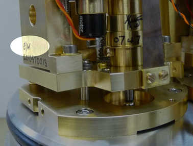
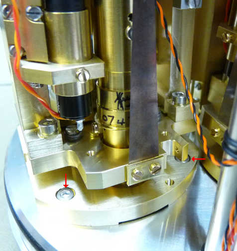
To lock the East/West sensor component, physically remove the whole locking assembly from the frame by by removing the three screws arrowed in the photo below:
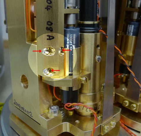
It should be possible to turn the cam with a small pair of pliers applied to the coupling sleeve on the gearbox output shaft. Do not apply pliers to the cam itself as you risk damaging the surface. If the cam cannot be turned, release the single motor clamp screw so that the motor and gearbox assembly can rotate as well. Turn the cam until its crown faces the point of contact with the spring, then remount the assembly. The mass will be locked as the screws are tightened.
Once the East/West sensor component is locked, remove the whole component by following the procedure below:
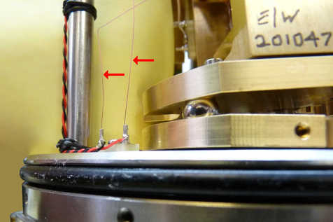
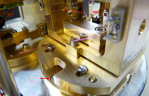
Locate the fine wires near the tilt base (marked by arrows in the photo below). Mark one or both wires so as to ensure correct reconnection, then de-solder them from the terminal posts.
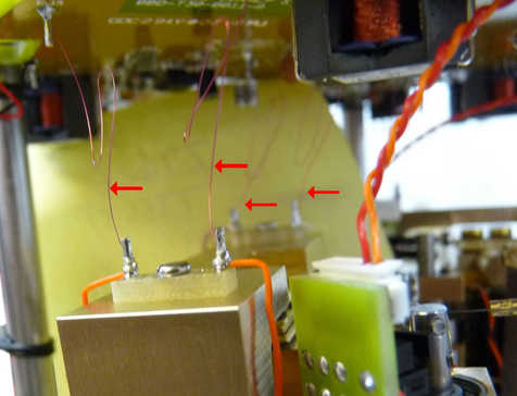
Similarly, locate, mark and de-solder the four upper fine wires:
Disconnect the cables to the locking motor at the connector shown:
Undo the three screws (arrowed in the following photographs) holding the component sensor to the instrument base:
You should now have easy, unencumbered access to the North/South sensor component. Repeat the locking procedure as for the East/West component.
For the vertical component sensor, the procedure is different. First try inserting a flat-headed screwdriver into the teeth of one of the driving gears - it is often possible to rotate the cam in this way.
If the gears cannot be rotated, it may be possible to release the grub-screw on the driving gear (the one on the gearbox output shaft) and turn the cam without turning the gearbox and motor. The grub-screw should be re-tightened afterwards.
If it still proves impossible to turn the cam, the motor can be released from its clamp, allowing it to turn in its mounting while the cam is being rotated. The clamp screw should be re-tightened afterwards.
3.5 Reassembly
Reassembly is the exact reverse of the disassembly procedure.