Chapter 3. The procedure
3.1 Equipment required
The following equipment is required:
2 mm hexagonal driver
 .
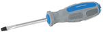
.Large, flat headed screwdriver
 .
.Anti-static workstation and wrist-band
 .
.Aluminium foil
 .
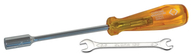
.An M3 (5.5 mm) spanner or nut-driver
 .
.General-purpose soldering equipment
 .
.
3.2 Material required
The following material is required:
a test lead with miniature clips
 .
. or
a short length (50 mm) of thin, insulated wire
 .
.
3.3 Working environment
The performance of the analogue sensor will be significantly reduced if it becomes contaminated with dust or air-borne particles. While this procedure does not directly expose the internal mechanics, it does involve opening the instrument and GSL recommend that this is only done in a clean, draught-free environment.
When working with any electronic systems, a properly grounded anti-static workbench or mat should be used, along with an anti-static wristband.
3.4 Disassembling the system
Use a 2mm hexagonal wrench to remove the six screws attaching the digital lid to the the cylinder.
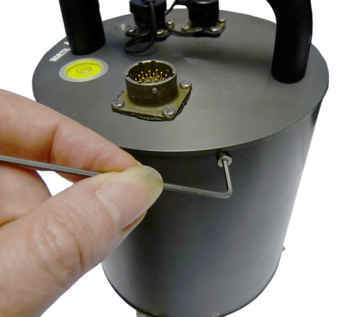
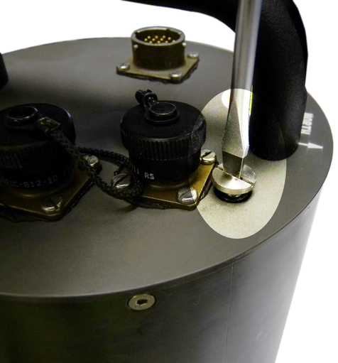
Use a large, flat-headed screwdriver to remove the pressure-relief screw from the lid of the instrument as shown in the following illustration.
Warning: Instruments are assembled near sea level. If working at altitude, there may be a considerable pressure difference between the inside of the instrument and local atmospheric pressure. Ensure that the pressure-relief screw does not fly off when released. Failure to do so may cause injury.
Remove the lid by holding the outer casing securely while gently pulling on the handle with a slight rocking motion. Be aware that there is a stack of PCBs fastened to the underside of the lid: do not allow them to knock against the inside of the tube as the lid is withdrawn.
Caution: The force required will drop significantly when the O-ring seal becomes clear of the the top of the tube. Take particular care that the lid does not “fly off” when this happens.
Lift the lid away from the tube and disconnect the ribbon cable at the lower end. Cover the top of the instrument with aluminium foil to prevent any contamination from entering the mechanical assembly.
3.5 Loading the emergency firmware
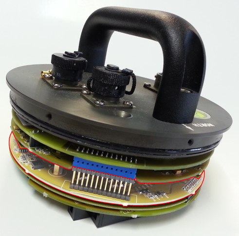
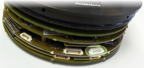
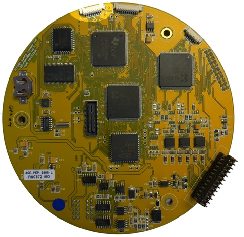
Working with the stack of PCBs attached to the instrument's lid, identify the processor board from the following photographs.
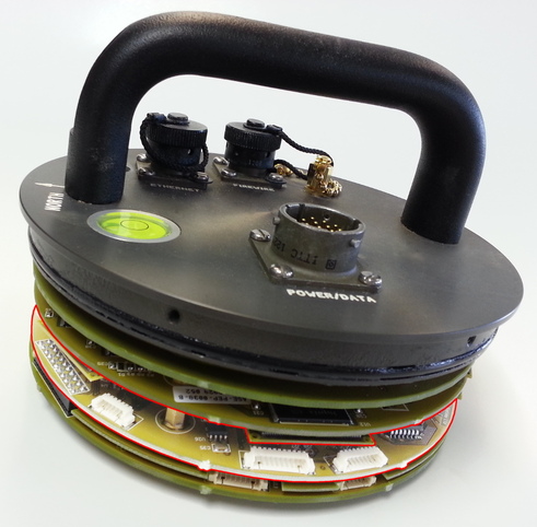
Note: The exact set of boards fitted depends on the instrument's age and features so the processor board may not be in the position shown in the photographs below. The board should be identified by the components or, if visible, a white paper sticker marked ASE-PEP-0008.
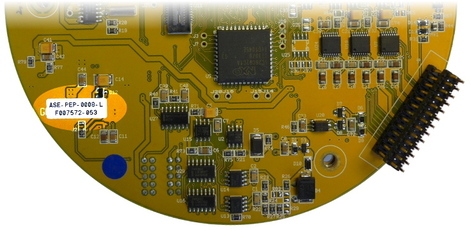
Identify the location for J5 on the edge of the processor board. Depending on the exact build of the instrument, there may or may not be a connector fitted in this position.
If there is no connector fitted, it is necessary to dismantle the stack until the processor board is fully accessible. Take careful note of the order in which the boards are removed and the orientation (both rotational and top/bottom) of each. Note also the positions of the various washers, which may be of different thicknesses. The must be refitted exactly as removed.
Connect pins 2 and 8 of J5, as shown:
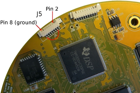
If a connector is fitted, this can be done with a test lead with miniature clips on each end. Alternatively, with the stack dismantled, you can solder a short wire link between the pads on the reverse of the board.
If the PCB stack has been dismantled, reassemble it now, ensuring that the boards are re-fitted in the correct order and orientation.
Connect the break-out box to the lid assembly. Power up the instrument's lid and connect a PC running a terminal emulator to the serial connector in the normal way.
The instrument will boot running the emergency firmware. This allows you to load the required firmware as described at
www.guralp.com//sw/firmware-for-newer-cmg-6tds-and-cd24s.shtmlOnce the required firmware is loaded, power down the lid and remove the wire link.
Note: If a wire link has been soldered into place, it can simply be cut rather than de-soldered, avoiding dismantling the stack again. In this case, ensure that the cut ends cannot touch any other components, including the instrument's tube once it is refitted.
3.6 Reassembling the system
Reassembly is essentially the reverse of the disassembly procedure but, please, do read this section to identify possible problems and to ensure that no steps are missed.
Inspect the 'O'-ring seal around the lid for any contamination. Clean and re-grease if necessary. Inspect the inside of the outer tube for any contamination. Clean if necessary.
Reconnect the the ribbon cable to the lid.
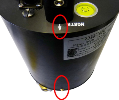
The bottom of the tube has two orientation studs, one brass and one steel. Aligning the “North” arrow to the brass stud, offer the lid to the instrument and reconnect the free end of the ribbon cable. Gently push the lid onto the tube and secure with six screws. Tighten the screws enough to be secure, but no tighter: over-tightening can distort the tube and compromise the seal.
Replace the pressure-relief screw in the lid. This screw incorporates an 'O'-ring seal: do not over-tighten or you will damage the 'O'-ring.
This completes the procedure.