Chapter 3. USB replacement procedure
3.1 Equipment required
The following equipment is required:
2 mm hexagonal driver.
Medium-sized, flat-bladed screw-driver.
Sharp knife or scalpel.
Anti-static workstation and anti-static wristband.
Single-component room-temperature vulcanizing silicone or equivalent silicone adhesive/sealing compound.
3.2 Disassembling the EAM
Remove the 4 thumbscrews securing the carrier assembly to the EAM body.
Remove the carrier assembly.
Use a 2 mm Allen key to remove the three screws attaching the the lid onto the casing as shown below:
Make alignment marks on the casing and lid so that they can be re-assembled in the correct orientation.
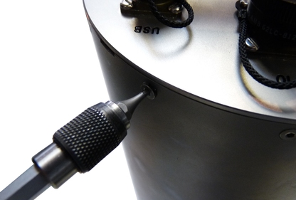
Lever off the lid by placing a flat headed screwdriver in the notches provided and twisting.
Caution: The force required will drop significantly when the O-ring seal becomes clear of the the top of the cylinder. Take particular care that the lid does not “fly off” when this happens.
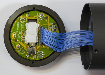
Lift the lid away from the cylinder as shown below. Do not worry if the ribbon cable becomes disconnected from either the lid or the PCB.
3.3 Replacing the USB memory device
Caution: ESD: The circuit boards contained within the instrument include components which can be damaged by electrostatic discharge. Always work on a properly grounded dissipative surface and wear a suitable grounded wristband. Ground yourself by touching an earthed conductor before handling any of the circuit boards.
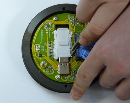
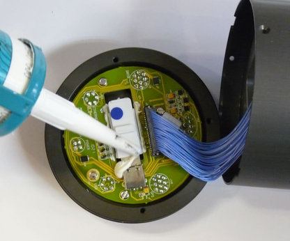
Locate the USB memory device, which is held in place using silicone. Using a scalpel or sharp knife, carefully remove the silicone from the USB memory device as shown:
Withdraw the memory device from its socket.
Carefully remove any larger loose lumps of silicone from the socket and PCB. It is not necessary to completely clean either; simply remove any loose pieces to provide a firm anchor point for the silicone that secures the replacement device.
If the replacement USB memory device is cased, remove the casing to free the memory carrier. When preparing devices at GSL, a small screwdriver is inserted into the recess in the base of the device and levered sideways to crack the casing open as shown:
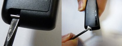
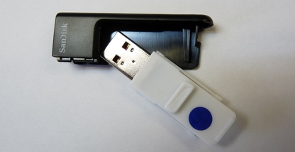
Note: At the time of writing (October, 2016), the USB memory devices currently supplied (ATP Endura) do not need to have their casing removed and this step can be ignored.
Insert the replacement memory device into the socket on the PCB.
Secure the memory device using a bead of silicone between the connector and device body as shown below. It is not necessary to apply silicone along the sides of the memory device.
3.4 Reassembling the EAM
Attach the ribbon cable if disconnected at step 6 during lid removal.
Install the lid onto the EAM case, ensuring the alignment marks line up. If the marks have rubbed off or are not clear, align the mounting holes for the carrier assembly with those at the opposite end of the cylinder.
Loosely install all the lid securing screws, then tighten.
Install the cylinder into the carrier assembly and secure using the four thumb screws.