Chapter 2. 2 First encounters
2.1 2.1 Handling notes
Although the 40V/H-1 has a rugged design, it is still a sensitive instrument, and can be damaged if mishandled. If you are at all unsure about the handling or installation of the device, you should contact Güralp Systems for assistance.
Avoid bumping or jolting the sensor when handling or unpacking.
Do not kink or walk on the data cable (especially on rough surfaces such as gravel), nor allow it to bear the weight of the sensor.
Do not connect the instrument to power sources except where instructed.
Do not ground any of the signal lines from the sensor.
All parts of the 40V/H-1 are waterproof.
2.2 2.2 Connections
The instrument has an integrated cable ending in a 26-pin mil-spec socket which carries both power and output signals. This is suitable for connecting directly to a Güralp digitizer.
 The breakout box, if ordered, provides individual signal and power connectors, or you can make up your own cable if you prefer.
2.2.1 The breakout box
If you are using a Güralp breakout box, it should be attached to the sensor through its SENSOR connector. Connectors are also provided at the CONTROL and RECORDER outputs, for attaching to a hand-held control unit or a Güralp digitizer. If you have ordered a 40V/H-1 with optional high gain outputs, you will need to make up a suitable cable to expose these outputs.
The breakout box also provides a standard Güralp power connector on a 10-pin mil-spec plug. The 40V/H-1 draws a nominal current of 48 mA from a 12 V supply when in use; thus, using a 12 V, 25 Ah sealed heavy-duty lead-acid battery, you should expect the instrument to operate for around a week without recharging.
The CENTRE button switches the instrument into ACC/VEL mode whilst it is pressed. This mode allows you to monitor the mass position whilst you adjust the offsets manually. If you prefer, you can use the equivalent switch on a Hand-held Control Unit (see below.)
2.2.2 The hand-held control unit
 This portable control unit provides easy access to the seismometer's control commands, as well as displaying the output velocity and mass position (i.e. acceleration) on an analogue meter.
2.2.2.1 Signal meter
The upper section of the HCU contains a simple voltmeter for monitoring various signals from the instrument.
To monitor the low-gain outputs, switch the dial to V LOW VEL (This applies to both vertical and horizontal instruments).
To monitor the high-gain output (on a 40V/H-1 with that option), switch the dial to V HIGH VEL.
To monitor the mass position output, switch the dial to V MASS POS. Whilst you are adjusting the mass position offset, you should also switch the instrument out of broadband mode by switching the rightmost CENTRING SELECT switch to 1 SEC VEL, or by holding down the CENTRE button on a breakout box.
You can set the range of the meter with the RANGE switch. When switched to 10 V, the meter ranges from –10 to + 10 V (as marked.) When switched to 1 V, the range is –1 to +1 V.
2.2.2.2 Calibration
You can calibrate a 40V/H-1 sensor through the HCU by connecting a signal generator across the yellow and green CALIBRATION SIGNAL inputs and setting the adjacent switch to ON. The sensor's response can now be monitored or recorded, and calibration calculations carried out. See Chapter 4, “Calibrating the 40V/H-1” for full details.
2.2.2.3 Control commands
If you have ordered a 40V/H-1 with the remote null facility, you can centre its mass from the HCU. To centre the mass:
Set the CENTRING SELECT dial to the V MASS POS setting;
Switch the rightmost switch to 1 SEC VEL to enable the centring lines; then
Press the +/– switch towards – to centre a mass from a positive value, or towards + to centre it from a negative value.
2.2.2.4 Banana plugs
The remainder of the HCU provides useful connections for each of the signal lines from the instrument, for attaching to your own equipment as necessary.
2.3 2.3 Zeroing the instrument
Before installing the 40V/H-1, you should check that the mass positions are not significantly offset from zero. The mass position offsets can be affected by any tilt to the instrument as well as rough handling during transportation. The normal range of the mass positions is ±10 V; you should zero the instrument if any mass reads more than around ±3.5 V when the sensor is stationary.
The velocity outputs of the 40V/H-1 are set at the factory to a nominal value below ±3 mV. Once the instrument is installed and has reached thermal equilibrium with its environment, these outputs should be similar to the factory-set value.
The CMG-40V/H-1 can be ordered with a option for automated “digital nulling”. See “Digital nulling operation” on page 10 for more information and instructions for using this function.
2.3.1 Adjusting the mass position offsets manually
The 40V/H-1 has a potentiometer (“pot”) accessible within its casing, which should be used to remove any DC offset electronically:
Bring the instrument into 1 second response mode by applying a voltage across the Acc/Vel and Signal Ground pins of the input. If you are using a DM24, you can do this by sending a CENTRE command. If you are using a Hand-held Control Unit, you should select 1 SEC VEL from the Velocity Select switch.
Measure the vertical mass position output with a 10 V voltmeter (see Appendix A, “Connector pin-outs”) or by selecting MASS POS, V from a Hand-held Control Unit's Display Select knob. If using a HCU, also check that the Centring Select knob is set to OFF.
If the sensor needs adjusting, it is necessary to remove the outer casing in order to gain access to an internal potentiometer. The outer casing is mounted onto the base with a greased screw thread. Before proceeding, place the instrument on a flat surface in a clean, indoor environment.
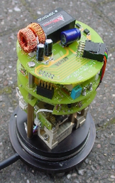 Holding the base firmly, carefully unscrew the entire casing as a unit. Lift off the casing vertically, making sure it does not catch on any of the components inside. You can safely run the sensor with the casing removed, as long as you do not touch any of the components.
Mounted above the sensor mechanics are three, stacked circuit boards. The centring can be altered by adjusting a potentiometer located on the top side of the lowest of the three boards.
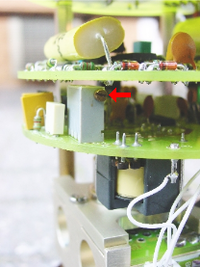 The adjustment is most easily made with a “trim-pot tool”. The mass does not have to be exactly centred, since you can compensate for any constant voltage offset afterwards. You should, however, ensure that the mass position will not clip under normal operation.
CMG-40V/H-1 sensors have a one second response, so the instrument should respond quickly to your adjustments.
After adjustment, carefully lower the outer casing over the instrument, being careful not to catch any of the components. Rest the casing on the screw-threads and turn anti-clockwise until you feel a click as the ends of the threads pass over each other. This avoids any danger of cross-threading. Now, holding the base firmly, screw the outer casing down until it engages moderately tightly against the base.
2.3.2 Adjusting the mass position offsets with a Hand-held Control Unit
Some 40V/H-1 units are equipped with a remote mass centring option, which allows you to adjust the internal potentiometers by applying voltages across control lines to the sensor:
Bring the instrument into 1 second response mode by selecting 1 SEC VEL from the Velocity Select switch.
Measure the vertical mass position output by selecting MASS POS, V from the Hand-held Control Unit's Display Select knob.
Set the Centring Select knob to V.
Press the spring-loaded switch towards + or – to bring the mass position offset from negative or positive values towards zero.
Return the instrument to broadband mode by selecting BB VEL from the Velocity Select switch.
2.3.3 Digital nulling operation
The CMG-40V/H-1 sensor can be ordered with an option for automated “Digital nulling'. This removes the need to manually adjust the internal potentiometers to achieve a near zero mass position output for each component. It comprises a micro-controller and three digital potentiometers that replace the standard electromechanical pots.
When installing the instrument, ensure that it is levelled accurately by checking that the bubble in the level lies within the central circle.
On power-up, the micro-controller will automatically zero the mass positions of all three axes simultaneously. Zeroing can be further triggered via the “centre” control line on pin U. (On instruments without the digital nulling option, pin U is the 'Acc/Vel' line).
Automatic zeroing takes approximately forty-five seconds to complete, after which the sensor reverts to long period operation and the nulling module enters a low power “sleep” mode. During nulling, the sensor's outputs will fluctuate as the pots are adjusted in a binary search before settling with a mass position of ±0.5V. If the sensor is poorly levelled, the micro-controller will make three attempts to zero the mass before giving up and using the closest match.
A test mode is available to check the operation of the digital centring pots. This mode is entered by holding the centre line low during power up. The unit will then set the pots to maximum for thirty seconds; then minimum for thirty seconds; then to the centre position for six minutes. The centre line must be held low continuously, otherwise the unit will abort the test mode and null the sensors as normal.
2.4 2.4 Installation notes
For the best possible results, a seismometer should be installed on a seismic pier in a specially-built vault, where conditions are near perfect. Here, wave-trains arriving at the instrument reflect very well the internal motion of subsurface rock formations. However, this is not always feasible. For example,
instruments may need to be deployed rapidly, perhaps to monitor the activity of a volcano showing signs of rejuvenation, or to study the aftershocks of a major earthquake;
installations may be required in remote locations, or otherwise in circumstances where it is infeasible to build a vault.
In these situations, the seismometer and its emplacement need to be considered as a mechanical system, which will have its own vibrational modes and resonances. These frequencies should be raised as high as possible so that they do not interfere with true ground motion: ideally, beyond the range of the instrument. This is done by
standing the sensor on bedrock where possible, or at least deep in well-compacted subsoil;
clearing the floor of the hole of all loose material; and
using as little extra mass as possible in preparing the chamber.
In temporary installations, environmental factors are also important. The sensor needs to be well protected against
fluctuations in temperature,
turbulent air flow around walls or trees, or around sharp corners or edges in the immediate vicinity of the sensor;
vibration caused by heavy machinery (even at a distance), or by overhead power lines.
This can be done by selecting a suitable site, and placing the instrument in a protective enclosure. An open-sided box of 5 cm expanded polystyrene slabs, placed over the instrument and taped down to exclude draughts, makes an excellent thermal shield.
After installation, the instrument case and mounting surface will slowly return to the local temperature, and settle in their positions. This will take around four hours from the time installation is completed.