Chapter 4. Setting the gain
The built in 5T sensor has a very large dynamic range. In order to exploit the whole of this range, two separate outputs are available, one with high gain and one with low gain. Normally, the high gain outputs are set to output a signal 10 times stronger than that from the low gain outputs. Only one set of outputs – low gain or high gain – is sent to the digitiser; the selection of which output to digitise is made using internal jumpers.
Note: To change the gain, it is necessary to open the instrument. This work must be carried out in a clean environment in order to prevent contamination of the mechanical components by air-borne dust.
Caution: The CMG-5TD include components which can be damaged by electrostatic discharge (ESD). Always work on a properly grounded dissipative surface and wear a suitable grounded wristband. Ground yourself by touching an earthed conductor before handling any of the circuit boards.
4.1 Disassembly
In order to change the gain-setting jumpers, remove the instrument's lid as follows:
Use a large, flat-bladed screwdriver to remove the pressure-release screw located on the instrument's lid next to the bubble-level.
Warning: GSL instruments are assembled at near to sea level. When using the instrument at altitude, there may be a considerable pressure differential between the air inside the casing and the external atmosphere. This could cause the screw to fly off with considerable force when initially released. Take care that this does not cause injury.
Use a small, flat-bladed screwdriver to remove the six small screws located around the edge of the top of the lid.
Note the location of the lid with respect to the body. Use a pencil or adhesive tape to mark both so that the instrument can be reassembled in the correct orientation.
Using a medium, flat-bladed screwdriver, gently prise the lid away from the body. A slot is provided in the top of the cylinder for this purpose.
Note: The lid-to-body seal uses 'O'-rings. Take care that the lid does not suddenly fly off when this seal is broken.
Lift the lid and the attached electronics vertically out of the cylindrical body and disconnect the ribbon cable at either end, noting the orientation of the cable.
Looking down into the body of the instrument, you will see a small printed circuit board mounted on an aluminium disc. This board contains the gain-setting jumpers, which are coloured red to aid identification.
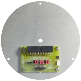
Each component (vertical, North/South and East/West) has two associated jumpers (one for each leg of the differential connection) and these must always be moved in pairs. It is possible to select different gains for different channels but this is rarely desirable. Consult the markings on the printed circuit board and the pictures below to select the desired gain.
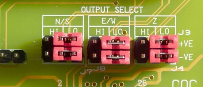
4.2 Jumper configuration for low gain operation
Arrange the jumpers as in the picture below:
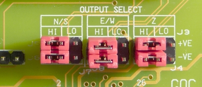
4.3 Jumper configuration for high gain operation
Arrange the jumpers as in the picture below:
4.4 Reassembly
Once the desired gain selection has been made, reconnect the ribbon cable and gently lower the lid onto the instrument, taking care not to knock the electronic assemblies or snag any cables. Ensure that the lid is rotated to the correct orientation using the marks you made previously and then gently ease it over the 'O'-ring seal and into place. Secure using the six small screws and, finally, replace the large pressure release screw.