Chapter 4. Working with strings
4.1 Introduction
Up to five instruments may be connected together in a daisy-chain configuration to form a flute string. Instruments may be connected together in any order and will auto-configure their identities: the top instrument will identify itself as sensor number one and lower instrument will assume sequential numbers.
Four special 20 m cables are provided to connect the instruments in a string configuration, together with a 300 m cable for suspension and connection to surface equipment. Only these cables should be used for string configurations.
4.2 Deployment
The following tools are provided for deployment:
Lifting cable termination
Cable trap plate.
To deploy the string:
Secure the end-cap to the bottom of the bottom-most sensor. This is essential to prevent ingress of moisture. The bottom of the sensor is the end opposite the hole-lock.
Caution: Deploying the instrument without the end-cap will result in poor vertical performance and moisture / water ingress, with consequential damage to the instrument.
Connect a 20 m string cable to the top of the bottom-most sensor and connect the lifting cable termination to the other end of this cable.
Winch this assembly into the bore-hole until the top of the cable is almost level with the top of the bore-hole.
Slide the cable trap plate over the cable and rest it on the top of the bore-hole.
Continue to winch the assembly down until the weight is taken entirely by the cable trap plate.
Remove the lifting eye cable termination from the cable.
Attach the bottom of the next sensor to the exposed cable.
Connect a 20 m string cable to the top of this sensor and connect the lifting eye cable termination to the other end of this cable.
Lift the deployed assembly slightly to allow the cable trap plate to be removed and then repeat from step 3.
When the final sensor has been connected to the deployed assembly, connect the 300 m cable to the top of the sensor.
Winch the entire assembly into the bore-hole to the required depth, using the integral lifting eye at the surface end of the 300 m cable.
Warning: The top connector and/or breakout cable should never be used to support the weight of the assembly. Use only the lifting-eye for this purpose.
Connect the Surface Control Unit (SCU) and hole-lock control unit to the top of the 300 m cable. Ensure that the main power switch is in the “OFF” position. Apply power (110 V to 240 V AC) to the hole-lock control unit and the SCU (but do not switch on the SCU yet).
Extend the hole-lock for the lowest (highest-numbered) sensor (see section 4.3.1).
Lower the remaining sensors a short distance so as to remove the tension from the 20 m interconnection cables, as shown below:
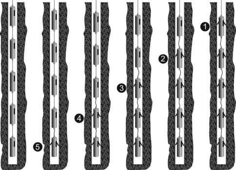
Extend the hole-lock for the next highest-numbered sensor then repeat from step 14.
Once all sensors are locked into the bore-hole, disconnect power from the hole-lock control unit and then disconnect the unit itself to prevent accidental unlocking.
4.3 Operation
4.3.1 Hole-locks
To operate the hole-lock, the hole-lock box must be attached to the surface box and mains (line) power (110-240 V 50-60 Hz.) must be applied to both boxes.
Switch the main power switch to the hole-lock position and turn the Hole-Lock select switch to the appropriate sensor. Sensor 1 is at the top of the string and Sensor 5 is at the bottom. Sensors are automatically numbered from the top of the string so if, for example, only 3 sensors are used, they will be numbered 1-3.
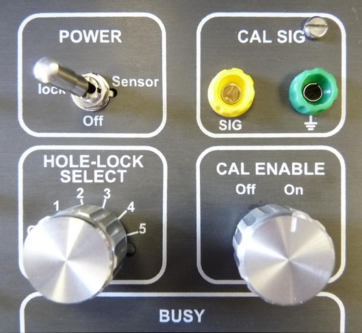
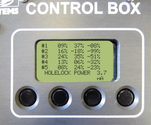
When the power switch is in the hole-lock position, the LCD screen will show the system current draw. This can be used to ascertain when the hole-lock is at one of its end-stops:
When the system is idle, there is a current draw of around 3-4 mA.
When the hole-lock is moving, there will be a current draw of around 10 mA at 1 bar pressure.
When the hole-lock motor is running, but the hole-lock is in contact with the casing tube a current draw of around 6 mA can be expected.
When the hole-lock hits an end-stop, the current will drop to idle values and it can be assumed the hole-lock is either fully deployed or fully stowed.
As the pressure around the hole-lock increases so the current draw increases proportionately.
4.3.2 Starting the sensors
To turn on the sensors in the string, move the main power switch to the “Sensor” position. The Surface box will then communicate with the sensors and label them, in turn, 1-5. Once this is done, normal operations can resume. During the labelling process, the centre lines are locked out, i.e. no external control of the centre lines will be available.
4.3.3 The LCD menu
When each sensor has been found, the mass positions will be obtained and displayed on the LCD and a “soft” menu pertaining to the functions of the four buttons below the LCD screen will be displayed. The functions of the buttons are:
Inclination, to report the inclination of each sensor in the string; and
Centre, to centre all the instruments in the string; and update the mass positions.
4.3.4 The “CAL ENABLE” switch
The “CAL ENABLE” switch will pull down the Calibration Enable line and tie all the signal grounds together, so that all the sensors can obtain a calibration signal at the same time. A calibration signal can be injected by using the banana plugs above the switch. Individual sensors may be enabled for calibration by using the serial interface.
4.3.5 The Response Line switches
These switches will set response of all sensors in the string to one, ten, thirty or sixty seconds. This only has effect if the default response of every sensor is set to Long Period (sixty seconds). This is the recommended way of configuring the responses of sensors in a string. If any sensors have a different default response set in software, it will affect all the others (setting them all to the fastest response configured).
Note: For this reason it is highly recommended that the sensor responses are not set using the serial or USB interfaces, but by use of the surface box..
4.3.6 The BUSY light
The Busy Light will flash when any sensor is awake and working (in a similar fashion to that described under single unit operation), but the initial flashing will not occur when using the USB or LCD unit as the surface box should be communicating with the sensors.
4.3.7 The USB interface
The USB interface provides a terminal interface. The USB interface will present as a COM port on a PC, via which the interface can be accessed using a terminal emulator, such as PuTTY or Minicom.
When the system is first powered up, a menu is displayed. A typical example is shown below:
I2C init
RESET by : PowerOn PIN
5Volt OFF
--------------------------------
MPE ROM PowerForth for Cortex-M3
v7.10 [build 0351] 14 Aug 2012, 17:13:06
================================
STM32L15x
Guralp Systems Ltd - 6TFSoH v1.0 mgs 14/08/12 (Build 0_43)
--------------------------------
STRING MASTER UDID 0038:0022:3130:3831:0747:3131 RS485 Master
3528 bytes free
LCD HCU found ..........
6TF Flute String Surface Control
Control Port : $4C ok
SYSTEM OFF
|+++++++++|++++ 14.6mA
HoleLock Power
|+++++++++|++++++ 16.5mA
SYSTEM OFF
|+++++++++|++++ 14.7mA
Sensor Power
|+++++++++|++++ 14.7mA
Scan for String Sensors
TOP
Wake....Hi Slave# 1
Wake....Hi Slave# 2
Wake....No reply
Wake....No reply No response?
2 Sensors in String
Mass Positions : Z N E
Slave# 1 Wake....Hi
MIKES STRING -40% -40% -40%
Slave# 2 Wake....Hi
IRIS TEST2 -38% -38% -39%
SURFACE MENU : Select Sensor # (1-2) to access
or S_tatus, R_esponse, C_alenable,
I_nclinations, A_ll centre
==========================================
|+++++++++|++++ 14.8mA
This example is from a string containing only two sensors. The surface menu will display more options of additional sensors are connected. The menu provides direct access to each sensor by keying the number corresponding to its position in the string ( ,
,  ,
,  ,
,  or
or  ).
).
When a number is keyed, a sensor menu is displayed.
The sensor menu provides these options:
1 Wake....Hi
********************************
6TF Control Menu : MIKES STRING
SENSORS : A_ll, V_ertical, N_orth, E_ast - centre
MODE : S_hortperiod, B_roadband
CONFIG : R_esponse, C_alenable
M_ass positions : I_nclination : O_ffset null ADXL : e_X_it :- KEY ?
The recognised inputs are shown in the table below:
Input | Function |
| Initiate centring of All components. |
| Initiate centring of the Vertical component only. |
| Initiate centring of the North/South component only. |
| Initiate centring of the East/West component only. |
| Place the instrument into one-second (Short-period) mode. |
| Place the instrument into Broadband (long-period) mode, as configured by the control lines (see section 3.3.4 on page 10). The actual period selected will be reported to the operator after this command has taken effect. |
| Allows the operator to select the default frequency Response of the sensor: i.e. the response that will be selected on power-up and after each centre is completed (but see section 4.3.5). Note that if the default is changed to MSP (medium-short period), Pin T will be low so pulling Pin S low will therefore result in a short period response and vice versa. DO NOT attempt to drive these lines high. |
| Toggle between enabling and disabling Calibration. |
| Print the current Mass position values. |
| Print the current Inclinometer outputs (in three axes). |
| Reset the inclinometer outputs to zero. This command is primarily for factory use and should only be issued when it is known that the instrument is accurately vertical. |
| Exit the command menu. The processor will check the mass positions, perform centring if required and then enter the low-power “sleep” mode. |


Note: When the instrument response is set using the menu system, the appropriate hardware response lines are pulled to ground. When used in a string configuration, this causes interactions between the different sensors in the string because each will respond to both hardware and software configuration. For this reason, it is strongly recommended that only hardware controls, such as those on the Surface Control Box, are used to set the frequency response of a Flute String.