Chapter 1. Introduction
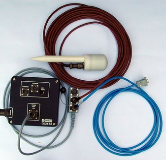
The CD24 is a compact, very low power, multi-purpose digitiser, with three 24-bit differential inputs and 8 lower-speed, single-ended auxiliary inputs. Equipment with analogue outputs connects to the CD24 via a 26 way mil-spec connector.
Key features include:
24-bit sigma-delta analogue to digital converters.
Low power: < 1W from 10V–28V DC.
±10V balanced differential input lines.
Lightweight and waterproof.
RS232 output in GCF (Güralp Compressed Format).
Multiple user-configurable output rates.
Once connected to 10 – 28 V DC power, the CD24 will begin operating automatically, digitising its inputs and either outputting digital data to your own recording system or saving them to internal Flash memory.
1.0.1 State of health information
The CD24 constantly monitors the status of the GPS and timing systems, outputting information in a plain text status stream.
An electronic thermometer also provides regular measurements of the unit's internal temperature, which are reported in the same stream. The thermometer is calibrated to an accuracy up to ± 0.33 °C, with a linearity of ± 0.5 °C.
1.1 Options
1.1.1 Storage and interfaces
The CD24 can be supplied with up to 16 Gb of internal Flash memory for data storage. The amount you need will depend on the length of your experiment and the sampling rates used.
You can download data from the internal storage:
over the RS232-compatible data port, directly into Scream! or other Güralp data modules;
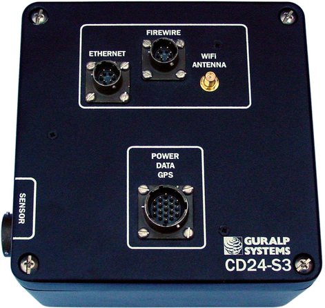
over a fast IEEE.1394 (FireWire) link with optional power; or
if fitted, using the Ethernet interface to transfer data over a local area or wireless network.
1.1.2 Wireless networking
The CD24 can be fitted with an optional 802.11b (“Wi-Fi”) wireless interface in addition to the Ethernet port. This option allows data flow to be established from autonomous installations with a minimum of setting up.
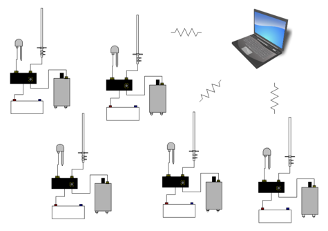
For temporary deployments, instruments and digitisers can be buried in shallow pits with only the antenna above ground. You can then contact to each station from a wireless-enabled PC running Scream! without disturbing the instrument, including monitoring real-time data and configuring the digitiser.
More permanent arrays also benefit from wireless technology, particularly in remote areas or where the terrain makes long cable runs impractical.
For example, stations might be installed with high-gain antennae directed towards a visible natural feature which is easier to access.
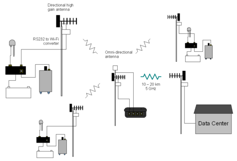
At this location, which can be up to 500 metres away, a low-power CMG-EAM data module might act as an access point for the array elements and forward data onto a higher-bandwidth radio link.
In semi-permanent arrays, a wireless-enabled CMG-EAM or laptop PC can be set up as a temporary access point for the duration of a site visit.