Chapter 6. Updating the CD24
The firmware of the CD24 can be updated remotely over its output port.
In Scream!’s main window, right-click on the digitiser's icon and select Terminal... from the pop-up menu. (If this fails, connect the digitiser directly to a serial port and right-click on the serial port instead.)
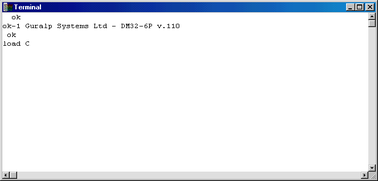
Check that there is two-way communication with the digitiser by pressing Enter. The digitiser should reply with ok on a new line. Type ok-1 to enable advanced commands. The digitiser will reply with a message describing the current firmware version.
If the firmware needs updating:
Type load and press ENTER. The digitiser will display
load C
and then wait for up to 10 seconds while the device is prepared for file upload.
Right-click on the terminal window and select Send file...:
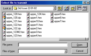
Firmware updates for the CD24 normally have filenames like upper_122.hex.
Choose the latest file and click Open.
If the file opens successfully, Scream! will show the progress of the upload:
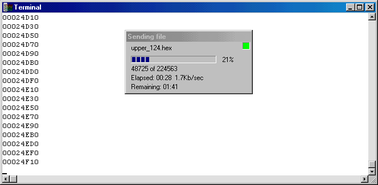
Depending on the speed of the link, it may take up to 20 minutes to transfer the firmware.
When the transfer completes, type re-boot to restart the CD24.
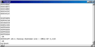
Allow 30 seconds for the digitiser to restart.
Right-click on the digitiser's icon in Scream! and select Configure... Check that the Software Version corresponds to the version you have just uploaded.
To check that the digitiser boots correctly after a cold start you may wish to power cycle the device.