Chapter 5. Command line interface
You can connect to the internal software of the CD24 over its output serial port and communicate with it.
To enter command mode from Scream!, right-click on the digitiser's icon and select Terminal... from the menu that pops up. A window will open, and once the CD24 and computer are communicating properly you will see the prompt
ok
If you prefer, you can use a terminal program of your own (such as minicom on Linux, or one of the programs detailed in section 7.5) to connect to the CD24.
Whilst you are in terminal mode, data transfer will be interrupted; the CD24 may use its Flash memory as a temporary store, depending on how you have configured it. Some commands, such as SET-TAPS, require a reboot to take effect.
Güralp Enhanced Acquisition Modules (CMG-EAM) also allow you to send commands direct to the CD24 using the command-line tools data-terminal and adc-command. For more information, please see the manual for the EAM.
If you have problems connecting to the digitiser's console, you should check that the serial port's options and baud rate are set correctly in Scream! or your terminal program. As supplied, the CD24 expects connections at 19200 baud, with 8 data bits, no parity bit and 1 stop bit. No flow control is used.
5.1 FORTH
The CD24 uses a FORTH-like interpreter to implement its features. To issue a command in FORTH, you must supply the arguments before the command, for example:
0 19200 BAUD
In FORTH, anything you enter is termed a word. New words (case insensitive) are placed on a stack. Some words are known to the system, and may represent commands; if a command finds itself at the top of the stack (e.g. because it is the last thing you typed), they will execute, remove themselves from the stack, and then remove further items from the stack to use as arguments.
Thus, in the command above, the numbers have no immediate effect, so stay on the stack. BAUD removes itself and the previous two items (here 0 and 19200) off the stack, then performs its action using these as arguments.
If a command completes with nothing remaining on the stack, the digitiser will show the prompt ok. Otherwise, no prompt will be given. Some commands, such as SAMPLES/SEC, clear the stack automatically after they execute. Pressing ENTER twice will always clear the stack.
Some commands are interactive, and will ask you to provide extra information after you execute them. In the following sections, interactive commands are shown as example sessions, where information you enter is given in bold and messages returning from the CD24 are given in medium.
Some of the less-used commands are not normally available over the terminal interface. In order to access these, you need to import them into the current dictionary with the command ok-1. You now have access to the full FORTH word list. To return to the normal state of the interpreter, issue the command [seal].
5.2 General configuration
5.2.1 SET-ID
Syntax: SET-ID (interactive)
Sets the system identifier and serial number of the CD24 to values you supply.
SET-ID
System Identifier ( WO3008 ) MYCD24
Serial # ? ( 123400 ) 4507
The system identifier you supply may contain up to 5 alphanumeric (0 – 9, A – Z) characters. The CD24 will pad any remaining space on the right with zeroes. If you want to use a system identifier less than 5 characters long, insert zeroes on the left to make it up to 5 characters. The digitiser will interpret leading zeroes as blank. (Because of this, you cannot have a system identifier that begins with a zero.)
The serial number you supply must contain 4 alphanumeric (0 – 9, A – Z) characters as shown. As for the system identifier, leading zeroes are interpreted as blanks.
5.2.2 BAUD
Syntax: port baud-rate BAUD
Sets the baud rate for one of the serial ports on the CD24, in bytes per second. The CD24 has a single port, numbered 0. For example,
0 19200 BAUD
This will reset a standard CD24 to its default configuration.
The allowable values for baud-rate are 4800, 7200, 9600, 14400, 19200, 57600 and 115200. Note especially that 38400 baud is not available on the CD24.
If you have a CD24 with Ethernet or Wi-Fi options, the settings you configure here are used both on the standard data output port, and on the internal port which sends data to the Ethernet/Wi-Fi module. If you change them, you will also need to configure the Ethernet/Wi-Fi module to receive data with the new settings. This can be done using the Lantronix DeviceInstaller utility (see section 2.3 on page 13 and section 7.4 on page 103.)
5.2.3 LOAD
Syntax: LOAD (interactive)
Starts an Xmodem file transfer for new CD24 firmware. For full instructions, see Chapter 6, page 81.
This command is in the extended dictionary; to use it, first issue the command ok-1 and finish with [seal].
5.2.4 LOAD-I
Syntax: LOAD-I (interactive)
Starts an Xmodem file transfer for a new Info Block. This block can be up to 1 K long, and will automatically be transmitted from the CD24 when it first powers up. You can use the Info Block to store any information you like: for example, about the digitiser, your project, or calibration data for attached sensors.
Before uploading an Info Block, you must convert it to Intel Hex format. Freely-downloadable tools exist that can help you with this conversion. Similar software is also available from Güralp Systems.
This command is in the extended dictionary; to use it, first issue the command ok-1 and finish with [seal].
5.2.5 TEMP?
Syntax: TEMP?
Display the current temperature measurement from the internal thermometer.
5.2.6 ETHER
Syntax: ETHER ENABLE | ETHER DISABLE
Enables or disables the optional Ethernet and Wi-Fi devices on the CD24.
When the Ethernet device is enabled, data produced by the CD24 will be sent to the device for transmission across the network, unless you have plugged a serial cable into the Data Out port of the breakout box. In this case, data will be sent over the standard RS232 interface only. This is the default behaviour.
When the Ethernet device is disabled, data will always be sent out over the standard RS232 interface, and the internal Ethernet/Wi-Fi module will not be used.
5.3 GPS and timing systems
5.3.1 GPS-TYPE
Syntax: type GPS-TYPE
Tells the CD24 which kind of GPS is attached to it.
type can be one of
0, if no GPS is available, or
2, for attached GPS equipment using the NMEA protocol.
5.3.2 HR-CYCLE
Syntax: interval HR-CYCLE
Sets the interval between GPS fixes. Under normal operation, the system will power on the GPS system every interval hours and synchronize its internal clock with GPS timing signals. Once the internal clock is sufficiently close to GPS time, the GPS system will be automatically powered down for another interval hours.
Setting interval to 0 will make the CD24 leave the GPS on continuously. This is recommended if your installation has access to mains power.
To find out the current HR-CYCLE setting, issue HR-CYCLE?
5.3.3 XGPS
Syntax: 0 XGPS | 1 XGPS
Manually switches on or off the GPS system, overriding the HR-CYCLE command (see above). If you issue 0 XGPS, the digitiser will switch off the relay; 1 XGPS will switch it on. Once the GPS system is switched on, the digitiser will automatically check the timing signal and synchronise its internal clock before switching off the GPS and returning to normal operation.
5.3.4 SET-RTC
Syntax: year month day hour minute second centisecond SET-RTC
Sets the system's real time clock. This time will be used from power-up until it is corrected by an attached GPS. If you are not using GPS but are synchronizing from some other time source, you will need to re-issue this command regularly to ensure the CD24 does not drift.
5.3.5 SET-CLOCK
Syntax: SET-CLOCK (interactive)
Sets the internal clock.
SET-CLOCK
Enter Date & Time -
YYYY MM DD HH MM SS
2006 02 01 12 53 25 Clock set 2006 2 1 12:53:27 ok
The time should be entered in the form year month day hour minute second, padding each field with zeroes so that they line up with the guide above.
If the CD24 does not recognize the time format you have used, it will output and error message.
This setting will be overridden when the GPS system next synchronizes the clock.
5.3.6 TIME?
Syntax: TIME?
Displays the current time as held in the system's real time clock. If a GPS is attached, this will be synchronized to it. The output is given in the form
year month day hour:minute:second ok
5.3.7 LEAPSECOND
Syntax: yyyy mm dd LEAPSECOND
Manually notify the digitiser of an upcoming leap second. This command is not normally necessary, since GPS already has support for leap seconds. However, some units do not properly interpret the GPS signals. See SQPATCH, below.
The leap second is taken to be at the end of the day yyyy-mm-dd.
5.3.8 SQPATCH
Syntax: SQPATCH ENABLE | SQPATCH DISABLE
Enables or disables the internal patch for older GPS receivers based on Trimble Lassen SQ units. These units misinterpret the GPS system's advance notification of a leap second, and consequently run one second slow until the leap second occurs.
With SQPATCH enabled, the time reported by the digitiser is offset by one second to counteract this problem. If you have set LEAPSECOND, above, SQPATCH will automatically be disabled when the leap second occurs, and the digitiser will then run normally.
GPS receivers with the latest firmware do not suffer from this problem.
To find out whether SQPATCH is currently enabled, issue the command .SQPATCH
5.4 Output configuration
5.4.1 SAMPLES/SEC
Syntax: tap-0 tap-1 tap-2 tap-3 samples/sec
The DSP software on the CD24 supports up to 7 cascaded filter/decimation stages. Each stage can be set to one of three decimation factors, which divide the sample rate by 2, 4 or 5. Decimation factors of 8 and 10 are also available, which the CD24 produces by combining two decimation stages. As a result, data can be output at up to 4 concurrent data rates. These configured output stages are called taps.
The ADC within the unit outputs data at 2000 samples/s, so taps can have sample rates between 1 and 1,000 samples/s.
The arguments tap-0 to tap-3 are the sample rates at each tap in turn, starting with the highest. You must ensure that each rate is lower than the previous one by a factor of 2, 4, 5, 8 or 10. Non-integer values are not allowed.
For example:
1000 250 125 25 samples/sec
500 100 5 1 samples/sec
200 100 20 4 samples/sec
400 40 20 10 samples/sec
As long as you specify the initial taps, you can omit later ones. The command fills in the value of the missing taps, using a decimation factor of 2 where possible. Thus, the following commands are equivalent:
400 40 20 10 samples/sec
400 40 samples/sec
5.4.2 SET-TAPS
Syntax: tap-0 tap-1 tap-2 tap-3 SET-TAPS
Sets which components are output under normal conditions, and at which tap(s).
tap-0 to tap-3 are integers below 8, whose binary bits represent the Z (1), N (2) and E (4) components respectively. Each one sets which components are output at that tap under normal conditions. You cannot set tap 0 to output streams.
For example, if you issue
1 5 7 0 SET-TAPS
then
tap 1 will output only the Z component (1);
tap 2 will output the Z and E components ( 1 + 4 = 5 );
tap 3 will output all three components ( 1 + 2 + 4 = 7 ); and
tap 4 will not output anything; and
To set triggered output streams, you should use the TRIGGERED command described below.
5.4.3 SET CONFIG
Syntax: SET-CONFIG
Selects which streams and mux channels are to be output as continuous data for each instrument. Two hexadecimal inputs are required as shown below:
SET-CONFIG
Hex code to select DSP#1 'taps' {0000,0000} 0070,0000
Hex code to select mux channels {00ff} 0307
The 8 digit hex code for the 'taps' is structured as follows:
ABCD,EFGH
A = Tap0 on Instrument B
B = Tap0 on Instrument A
C = Tap1 on Instrument B
D = Tap1 on Instrument A
E = Tap2 on Instrument B
F = Tap2 on Instrument A
G = Tap3 on Instrument B
H = Tap3 on Instrument A
Each component within a tap on an instrument is given a binary value:
1 = Z
2 = N/S
4 = E/W
8 = X (the auxiliary input, present on 4 and 8 channel systems only)
The value at each of the eight hex code positions is the total of the values of the required components, expressed in hexadecimal. For example:
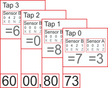
In the above example the following data outputs are activated:
N and E from Sensor B at Tap 3
No outputs from Sensor B at Tap 2
X channel from Sensor B at Tap 1
Z, N and E from Sensor B at Tap 0
Z and N from Sensor A at Tap 0
Further examples:
To set the N component at Tap 2 of Instrument A, the hex code would be:
0002,0000
To set the all 3 components at Tap 3 of Instrument B, the hex code would be:
0000,7000
The Hex Code for the Mux channels is configured in much the same way:
ABCD
A = M0 to M3
B = M4 to M7
C = M8 to MB
D = MB to MF
The least significant bit is the lower channel within each group (i.e. M0 = 1 and M3 = 8).
For example, to configure mass position outputs for the first instrument (M9, MA and MB), the required code would be:
0070
Note:
M8 = Z Mass position
M9 = N/S Mass position
MA = E/W Mass position
MB = Calibration signal (on 3 channel digitisers)
ME = Temperature
5.4.4 COMPRESSION
Syntax: bits size COMPRESSION or NORMAL COMPRESSION
Sets the maximum amount of compression to use. Greater compression means the digitiser outputs data more efficiently, so more can be transmitted over a link with a given bandwidth. However, compressing streams uses processor power and can increase data latency.
The digitiser compresses data without loss, so compression is most effective when the data contain relatively little information. In most cases, when a seismic event occurs, the digitiser will need to decrease the compression level.
bits can be one of 8BIT, 16BIT and 32BIT. 8BIT (the default) is the maximum amount of compression; 32BIT denotes no compression.
size determines the maximum number of data samples in a GCF block. This must be between 20 and 250; the default is 250.
GCF blocks must be a whole number of seconds long. If you set size to a very small value, so that size samples is less than 1 second for some streams, the digitiser will output 1 block every second for those streams, ignoring the value of size.
Thus, if you issue 32BIT 20 COMPRESSION, streams with a sample rate of 20 samples/s and higher will output one block per second, whilst lower rate streams will output 20-sample blocks: every 5 seconds for 4 samples/s data, etc.
The special value, NORMAL COMPRESSION, returns the setting to its default value, and is equivalent to 8BIT 250 COMPRESSION.
5.5 Triggering
5.5.1 TRIGGERS
Syntax: components TRIGGERS
Selects which component or components can generate a trigger. Only these components will be examined by the triggering algorithm.
components is an integer below 16, whose binary bits represent the Z (1), N (2), E (4) and auxiliary (8) components respectively. Thus, for example,
1 TRIGGERS will trigger from the Z component only (1);
6 TRIGGERS will trigger from either the N or E components (2 + 4 = 6);
7 TRIGGERS will trigger from any of the three components (1 + 2 + 4 = 7);
0 TRIGGERS will disable the triggering system.
5.5.2 TRIGGERED
Syntax: tap components TRIGGERED
Selects which component or components will be output when a trigger is generated, and at which tap (sample rate).
tap is the tap number at which to output the triggered stream. You can set which taps output which sample rate using the SAMPLES/SEC command, described above.
components is an integer below 16, which represents which components to output in the same fashion as in the TRIGGERS command, above.
(These two commands have similar names; remember that a component TRIGGERS the system, whilst taps and components can be TRIGGERED.)
5.5.3 STA
Syntax: Z-secs N-secs E-secs STA
Sets the length of the “short-term” averaging period in the STA/LTA triggering algorithm.
Z-secs, N-secs, and E-secs are the time period over which to calculate the average for the Z, N, and E components respectively. If a component is not considered by the triggering algorithm (see TRIGGERS, above), the value you specify here will be ignored.
For example, 1 2 2 STA will calculate short-term averages for 1 s of the Z component, and 2 s of the horizontal components.
5.5.4 LTA
Syntax: Z-secs N-secs E-secs LTA
Sets the length of the “long-term” averaging period in the STA/LTA triggering algorithm.
Z-secs, N-secs, and E-secs are the time period over which to calculate the average for the Z, N, and E components respectively. If a component is not considered by the triggering algorithm (see TRIGGERS, above), the value you specify here will be ignored.
For example, 15 20 20 STA will calculate long-term averages for 15 s of the Z component, and 20 s of the horizontal components.
5.5.5 RATIOS
Syntax: Z-ratio N-ratio E-ratio RATIOS
Sets the ratio of STA to LTA above which a trigger will be declared in the STA/LTA triggering algorithm.
Z-ratio, N-ratio, and E-ratio are the time period over which to calculate the average for the Z, N, and E components respectively. If a component is not considered by the triggering algorithm (see TRIGGERS, above), the value you specify here will be ignored.
For example, 4 10 10 RATIOS will cause the CD24 to trigger if the STA/LTA ratio is above 4 for the Z component, or above 10 for the horizontal components.
5.5.6 BANDPASS
Syntax: tap filter BANDPASS
The CD24 passes the stream(s) which generate STA/LTA triggers through a band-pass filter before examining them. This filtering does not affect the continuous outputs. The corner frequency of the band-pass filter can be changed with the BANDPASS command.
filter = 1 creates a filter with a corner at 10 % of the Nyquist frequency for tap tap (i.e. 5 % of its sample rate)
filter = 2 creates a filter with a corner at 20 % of the Nyquist frequency for tap tap (i.e. 15 % of its sample rate)
filter = 5 creates a filter with a corner at 50 % of the Nyquist frequency for tap tap (i.e. 25 % of its sample rate)
5.5.7 MICROG
Syntax: level MICROG
Sets the output level above which a trigger will be declared when using the LEVEL triggering algorithm. level is interpreted in counts. To interpret in ground units use MICRO-G.
5.5.8 MICRO-G
Syntax: level MICRO-G
Sets the output level above which a trigger will be declared when using the LEVEL triggering algorithm. level is interpreted in ground units (μg) if there is a correctly populated infoblock (calvals), otherwise the level will be interpreted in counts (see MICROG).
5.5.9 HIGHPASS
Syntax: filter HIGHPASS
Instructs the digitiser to pass the stream(s) which generate LEVEL triggers through a high-pass filter before examining them. filter can be:
1, for a 100 s high pass filter;
2, for a 300 s filter;
3, for a 1000 s filter; or
0, to disable the high pass filter.
Note that this filter will affect the data being output as continuous streams.
5.5.10 PRE-TRIG
Syntax: time PRE-TRIG
Sets the pre-trigger recording time. time is the number of seconds of data to output from before a trigger is declared.
5.5.11 POST-TRIG
Syntax: time POST-TRIG
Sets the post-trigger recording time. time is the number of seconds of data to output after a trigger condition lapses. If an event persists for some time, all triggering components must fall below the threshold before the trigger condition will lapse; only then will the post-trigger period begin.
5.5.12 TRIGGERIN
Syntax: TRIGGERIN ENABLE | TRIGGERIN DISABLE
Enables or disables external trigger input, in digitisers equipped with this option.
Enabling external trigger input allows you to trigger the CD24 from an external logic level supplied through its digital output port. This voltage can be between 5 and 10 V supplied between the Trigger In pin and signal ground. If the CD24 is triggered externally, it will behave exactly as if it had generated the trigger itself.
5.5.13 TRIGGEROUT
Syntax: TRIGGEROUT ENABLE | TRIGGEROUT DISABLE
Enables or disables external trigger output, in digitisers equipped with this option.
Enabling external trigger output allows you to trigger other equipment through a relay contained within the CD24 whenever it triggers. The CD24's digital output port contains two pins (Trigger out, common and Trigger out, normally-open) which are connected when it triggers. In particular, you can connect a second digitiser with TRIGGERIN ENABLE in effect, in which case triggered data from both instruments will be transmitted whenever the CD24 triggers.
If a CD24 has both TRIGGERIN ENABLE and TRIGGEROUT ENABLE in effect, only triggers which the CD24 itself has generated will be output. Triggers received through the Trigger in port will cause the CD24 to output triggered streams, but will not be passed on to other digitisers.
5.6 Calibration
5.6.1 SINEWAVE
Syntax: component freq-or-period unit SINEWAVE
Instructs the CD24 to inject a sine-wave calibration signal, starting on the zero crossing.
component specifies which component is to be calibrated, one of Z, N/S, or E/W.
freq-or-period and unit together determine the frequency of the calibration signal. If unit is HZ, then freq-or-period is taken as a frequency, in Hz; if SECOND, then it is interpreted as a period, in s. For example:
N/S 4 HZ SINEWAVE
freq-or-period must be an integer; if you want to specify a period of, for example, 0.5 s, you should specify it as 2 HZ instead.
The calibration signal will be automatically disconnected after 2 minutes if you have not altered the setting using the MINUTE command, described below.
5.6.2 SQUAREWAVE
Syntax: component SQUAREWAVE
Instructs the CD24 to inject a square-wave (step function) calibration signal, consisting of a positive step on the start of the next clock minute, followed by a negative step some minutes later (by default, 2). The calibration is disconnected the same number of minutes after the negative edge.
component specifies which component is to be calibrated, one of Z, N/S, or E/W.
You can alter the duration of each step using the MINUTE command, described below.
5.6.3 RANDOMCAL
Syntax: component RANDOMCAL
Instructs the CD24 to inject a white-noise calibration signal generated by an onboard pseudo-random number generator.
component specifies which component is to be calibrated, one of Z, N/S, or E/W. Some sensors use only the Z calibration loop for all three components.
The calibration signal will be automatically disconnected after 2 minutes if you have not altered the setting using the MINUTE command, described below.
5.6.4 MINUTE
Syntax: duration MINUTE
Sets for how long the next SINEWAVE calibration signal will be injected, or the period of the next SQUAREWAVE calibration signal.
duration is the desired interval, in minutes. If you now issue a SINEWAVE command, the calibration will last duration minutes; if the next calibration command is SQUAREWAVE, a positive step of duration minutes will be generated, followed by a negative step of a further duration minutes.
If you do not issue MINUTE, calibration signals will default to 2 minutes. This is to avoid the sensor and digitiser inadvertently being left in calibration mode. Issuing, e.g., 5 MINUTE will cause the next calibration signal to last 5 minutes, but later calibration signals will revert to a duration of 2 minutes. You will need to issue a MINUTE command before each injection.
Because of the way FORTH works, you can insert MINUTE commands into SQUAREWAVE or SINEWAVE commands, for example:
N/S 4 HZ 5 MINUTE SINEWAVE
E/W 10 MINUTE SQUAREWAVE
5.6.5 %AMPLITUDE
Syntax: percentage %AMPLITUDE
Sets the calibration amplitude to the given percentage of the full-scale signal.
5.7 Actions
5.7.1 CENTRE
Syntax: CENTRE or CENTER MONITOR
Centres the sensor mass(es) of the instrument.
CENTRE returns immediately, whilst CENTRE MONITOR monitors the progress of the unlock by displaying mass positions, as for LOCK MONITOR (above).
When the masses are correctly centred, the mass positions should read less than ±1000 counts.
5.7.2 %AUTO-CENTRE
Syntax: distance %AUTO-CENTRE
Instructs the CD24 to perform a round of centring whenever a mass position drifts further than distance from zero. distance is measured as a percentage of full scale.
Setting distance to zero disables automatic centring.
5.7.3 RESP
Syntax: value RESP
The CD24 provides a 1 second response mode for use when monitoring mass positions or adjusting offsets. To enter this mode, issue the command 1 RESP.
Once you have finished monitoring the mass positions, you can return to broadband response mode by issuing 0 RESP.
5.7.4 MASSES?
Syntax: MASSES?
Displays the current, instantaneous position of the three sensor masses, in counts (range ±8 000 000):
masses? z-position n/s-position e/w-position ok
5.7.5 RE-BOOT
Syntax: RE-BOOT
Causes the CD24 to reset. Some configuration changes will only take effect after you have rebooted the digitiser.
5.8 Flash storage and filing
5.8.1 SHOW-FLASH
Syntax: SHOW-FLASH
Reports status information about Flash memory in the CD24. For example:
SHOW-FLASH for a new system with 8 × 64Mb chips fitted:
show-flash FILESTORE C 0000FFFF00000000
FILESTORE K 1048160
Last Flush: CHIP - -1 0000FFFF
Last write: CHIP – 35 00000FF8 ok
The first two lines display internal diagnostic information, whilst the last two lines describe the position in Flash
where data was last flushed, and
where data was last written.
5.8.2 DOWNLOAD
Syntax: DOWNLOAD (but see below)
Sets up a data transfer from the Flash memory over the serial connection direct to SREAM! or other software.
SCREAM! Can be configures to auto-record data. Refer to the manual for more information.
The flash memory is used as a ring buffer. Two pointers into the memory keep track of where data were last read (the “Read Pointer”) and last written (the “Write pointer”). When either pointer reaches the end of physical memory, it wraps round back to the beginning. The behaviour when the write pointer reaches the read pointer (i.e. when the memory becomes full of data, none of which have been downloaded) is governed by the commands RE-USE/RECYCLE and WRITE-ONCE.
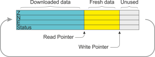
Which data are downloaded depends on various parameters you can set, which allow you to select a particular stream, streams of a specified sample rate, or streams within a certain time window. You can set parameters separately, or place the definitions before the DOWNLOAD command, e.g.
ALL-FLASH HPA0N1 STREAM DOWNLOAD
2004 12 01 00 00 FROM-TIME ALL-DATA DOWNLOAD
100 S/S ALL-TIMES DOWNLOAD
ALL-DATA ALL-TIMES DOWNLOAD
Before DOWNLOAD will work, it needs to know
the desired time period, which is specified with ALL-FLASH, ALL-TIMES, or FROM-TIME and/or TO-TIME, and
the streams you want to download, which are specified with ALL-DATA, S/S, or STATUS-ONLY.
The parameters are illustrated in the diagram below and fully described in the following sections. If you miss out a parameter, DOWNLOAD will use the value you last used.
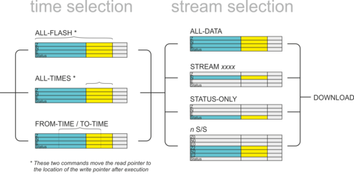
The DOWNLOAD command returns immediately, so that you can issue more commands if required. To close the connection and begin downloading, issue the GO command.
You can pause a download by entering terminal mode, and restart with another GO or abort with END-DOWNLOAD.
When you complete a DOWNLOAD without specifying a time period, the CD24 marks the latest position with an internal read pointer, which can be used as a start point for the next DOWNLOAD with the command ALL-TIMES (see below.)
5.8.3 ALL-FLASH
Syntax: ALL-FLASH
Moves the read pointer to the oldest data held by the CD24, and sets up the DOWNLOAD to transfer all data since then. When it has finished, the read pointer will be at the end of the downloaded data.
This command does not alter which streams are to be transmitted; you should also specify streams or use the ALL-DATA command.
When you issue ALL-FLASH, the old position of the read pointer is forgotten. Issuing ALL-TIMES will not restore it.
5.8.4 ALL-TIMES
Syntax: ALL-TIMES
Clears any time selection in force. The next DOWNLOAD will begin at the read pointer, and end with the newest data. When it has finished, the read pointer will be moved to the end of the downloaded data.
5.8.5 FROM-TIME
Syntax: yyyy mm dd hh mm FROM-TIME
Instructs the CD24 to transmit only data more recent than yyyy-mm-dd hh:mm, where
yyyy is a four-digit year (1989 – 2069);
mm is the month number (1 – 12);
dd is the day of the month (1 – 31);
hh is the hour of the day (0 – 23); and
mm is the minute of the hour (0 – 59).
5.8.6 TO-TIME
Syntax: yyyy mm dd hh mm TO-TIME
Instructs the CD24 to transmit only data earlier than yyyy-mm-dd hh:mm, where yyyy, mm, dd, hh and mm have the same meanings as in FROM-TIME, above.
You can combine FROM-TIME with TO-TIME to download data from a specific time window.
When a TO-TIME download completes, the read pointer will be moved to the end of the downloaded data. The old position of the read pointer is forgotten, so issuing ALL-TIMES may transmit data you have previously downloaded.
5.8.7 ALL-DATA
Syntax: ALL-DATA
Instructs the CD24 to transmit all the data streams it holds next time a DOWNLOAD is issued. This command does not alter the read pointer or specify a time period.
5.8.8 STREAM
Syntax: STREAM stream-id (n.b.)
Instructs the CD24 to transmit only the stream with ID stream-id. Stream IDs are normally a 4-character device code (e.g. HPA0) followed by a component letter (N) and a tap number (1).
Unlike most FORTH commands, the stream-id parameter goes after the command.
The read pointer will be moved to the end time of the download, so a subsequent ALL-TIMES DOWNLOAD will not transfer any other streams that were recorded during this period. To retrieve these streams, you will have to specify the time period explicitly with FROM-TIME (and TO-TIME if necessary), or download all stored data with ALL-FLASH.
5.8.9 STATUS-ONLY
Syntax: STATUS-ONLY
Instructs the CD24 to transmit only status streams (text streams, normally with stream IDs ending in 00.)
The read pointer will be moved to the end time of the download, so a subsequent ALL-TIMES DOWNLOAD will not transfer any data streams that were recorded during this period. To retrieve these streams, you will have to specify the time period explicitly with FROM-TIME (and TO-TIME if necessary), or download all stored data with ALL-FLASH.
5.8.10 S/S
Syntax: rate S/S
Instructs the CD24 to transmit only streams with sample rates equal to rate. If rate is zero, only status streams are transmitted.
The read pointer will be moved to the end time of the download, so a subsequent ALL-TIMES DOWNLOAD will not transfer any other streams that were recorded during this period. To retrieve these streams, you will have to specify the time period explicitly with FROM-TIME (and TO-TIME if necessary), or download all stored data with ALL-FLASH.
This command should not be confused with the SAMPLES/SEC command.
5.8.11 RESET-FLASH
Syntax: RESET-FLASH
Resets the Flash memory pointers so that both point to the start of physical memory. The CD24 will start overwriting old data from the beginning of memory. You can still access these data, if they have not been overwritten.
5.8.12 ERASEFILE
Syntax: ERASEFILE (interactive)
Clears the entire Flash memory. When you issue this command, the CD24 will ask you for confirmation. Enter y to confirm.
You will not be able to access any data previously held in Flash memory after issuing this command.
5.9 Transmission modes
The CD24 operates in one of several transmission modes. These modes relate to how the unit uses its Flash memory. For more details, see section 3.2.5, page 40.
5.9.1 DIRECT
Syntax: DIRECT
Instructs the CD24 not to use Flash memory for storage. Instead, all data are transmitted directly to clients.
5.9.2 FILING
Syntax: FILING
Instructs the CD24 not to transmit blocks to clients automatically, but to store all digitised data in the Flash memory. The memory is used in circular fashion, i.e. if it becomes full, incoming blocks begin overwriting the oldest in memory.
You can retrieve blocks from a digitiser in FILING mode by connecting to its terminal interface and issuing DOWNLOAD commands, or by transferring the data to a FireWire disk.
When in FILING mode, a digitiser transmits “heartbeat” messages over its data port. These short messages take the place of blocks, and ensure that programs such as Scream! know that a digitiser is present. You can change the frequency of heartbeat messages using the command HEARTBEAT.
5.9.3 DUPLICATE
Syntax: DUPLICATE
Instructs the CD24 to transmit all new data directly to clients (as in DIRECT mode) as well as storing it in Flash memory (as in FILING mode). If a client fails to acknowledge a block, the digitiser does not attempt to retransmit it.
5.9.4 DUAL
Syntax: DUAL
Instructs the CD24 to transmit any continuous streams directly to clients (as for DIRECT mode) but to store triggered data into Flash storage (as for FILING mode.)
If you choose this mode, the digitiser will send heartbeat messages in addition to any continuous streams you have configured. Scream! can pick these up and download new data as necessary.
5.9.5 ADAPTIVE
Syntax: ADAPTIVE
Instructs the CD24 to transmit current blocks to clients if possible, but to store all unacknowledged blocks in the Flash memory and re-send them, oldest first, when time allows.
5.9.6 FIFO
Syntax: FIFO
Instructs the CD24 to begin writing blocks to Flash memory as for FILING, but also to transmit data to clients. Data are transmitted in strict order, oldest first; the CD24 will only transmit the next block when it receives an explicit acknowledgement of the previous block.
5.9.7 HEARTBEAT
Syntax: interval HEARTBEAT
When the CD24 is in FILING mode, it outputs status messages periodically over the RS232 port. This command changes how often these messages are produced.
interval is measured in units of 30 ms. For example, issuing
600 HEARTBEAT
will cause the CD24 to output heartbeat messages every (600 × 30) = 18000 ms = 18 s.
If you connect to a digitiser in FILING mode using Scream!, Scream! will not detect the digitiser until it has sent a heartbeat message. Therefore, you should use a relatively short heartbeat interval if you have a continuously-connected digitiser.
5.9.8 MS-GAP
Syntax: interval MS-GAP
Sets the interval the digitiser should wait for a GCF ACK (acknowledged) message, before assuming that the block could not be transmitted.
If a period of interval passes without an acknowledgement, the digitiser's behaviour depends on the current transmission mode (see above.)
interval is measured in milliseconds. The default is 150. If the value is greater than the average time between blocks being generated, and an outage occurs in the return communications link, the digitiser will be producing data faster than it can transmit them, and gaps will start to be observed. However, systems using slower communications links (e.g. radio links) may be unable to acknowledge blocks in under 150 ms. You should choose a value for interval which is suitable for your particular installation.
5.10 Buffering Modes
5.10.1 RE-USE
Syntax: RE-USE
Instructs the CD24 to use its Flash memory as a circular buffer, overwriting the oldest data when it becomes full.
In this mode, the Flash memory will always contain the latest data.
5.10.2 WRITE-ONCE
Syntax: WRITE-ONCE
Instructs the CD24 not to overwrite data in the Flash memory when it becomes full Instead, when the digitiser runs out of space, it switches to DIRECT transmission mode and will leave the Flash memory untouched.
5.10.3 MODE?
Syntax: MODE?
Displays the current buffer usage mode (RE-USE = Circular; WRITE-ONCE = Write Once.)
5.11 FireWire disks
5.11.1 DIR
Syntax: DIR
Displays the contents of the FireWire disk as a directory listing.
dir N00000002
V31333934
Logon0000C000 00000000
@L00000000,00100000,0000FFC1
FW INIT
DISKSIZE K 60051600
STREAM | start | finish | length
620600 18 2002 12 13 15:08:50 2096304 2001 01 C5 04:43:24 2096288
Diskfree (sectors) 118006880
Diskfree (MB) 57620
ok
The first lines give general status information about the storage available, followed by the directory itself—notably
N00000002 : the number of devices connected to the hub (here, 2);
FW INIT : denotes that the disk was successfully mounted;
DISKSIZE K 60051600 : the size of the device, in kilobytes;
620600 : the stream ID of the sensor;
18 : the starting cluster number;
2002 12 13 15:08:50 : the date and time of the earliest block in memory;
2096304 : the end cluster number;
2001 01 C5 04:43:24 : the date and time of the latest block in memory;
2096288 : the total number of clusters of data held.
If there is no disc connected, or the cable is faulty, you will see the message FW Ierr (i.e. input/output error).
5.11.2 FLUSH
Syntax: FLUSH
Starts transferring data from Flash memory to an attached IEEE.1394 (FireWire) device, starting at the point where the previous FLUSH ended (if any.) The CD24 remembers the new flush point, so that next time you issue FLUSH no data will be repeated.
If you want to transfer the entire Flash storage, use FLUSHALL instead.
During the transfer the CD24 will report the sector numbers that are being transferred:
flush Last Flush : 00200056 2002 12 17 09:22:22
00200056 Starting Transfer 00200056
CHIP – 00200056
00200812
00201012
00201812
...
Transfer Finished
If no data have been written to Flash since the last FLUSH, you will see the message No data to save.
If there is no disc connected, or the cable is faulty, you will see the message No disk found.
5.11.3 FLUSHALL
Syntax: FLUSHALL
Transfers all the data currently in Flash storage, and updates the FLUSH pointer so that subsequent FLUSH operations do not duplicate the data.
5.11.4 RESET-DISC
Syntax: RESET-DISC | RESET-DISK
Resets the FAT (file allocation table) of a Firewire disc, so that it contains no files. You should only use this command if you want to overwrite any data already on the disc. You will be asked for confirmation before the operation proceeds.
In emergencies, you may be able to recover data from a disc which has been erroneously reset by dumping the disc contents directly onto your computer (with dd or a similar direct read tool), as long as you have not allowed new data to overwrite the old.
If there is no disc connected, or the cable is faulty, you will see the message FW Ierr.