Chapter 4. STA/LTA triggering
In its standard configuration the digitizer outputs continuous data at a user-selectable sample rate. An additional powerful feature of the digitizer is the ability to simultaneously run a STA/LTA event triggering algorithm in parallel with the continuous acquisition. This permits the system to record continuously at a relatively low sample rate, and record at a much higher sample rate during short periods when triggered. Parameters controlling the triggering algorithm, and controlling the data output once the system is triggered, are all selectable by the user, permitting the maximum flexibility of operation and the most efficient use of available storage space.
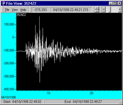
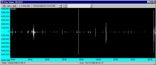
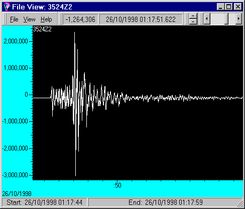
Shown above in the upper window, is an example of a data stream recording over a two month period. Two seismic events are shown highlighted in the two lower windows which, given suitable triggering parameters, can be recorded in greater detail at a higher sampling rate of upto 200 samples per second.
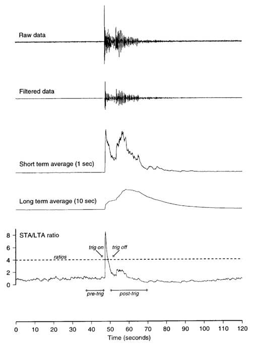
Triggering of all three components from vertical channel 100Hz tap, filter from 5 to 45 Hz
Sta = 1, Lta = 50, Sta/Lta = 10, pre-trigger = 40, post-trigger = 70
This section describes the triggering algorithm and gives several examples of typical system configurations that may be used. It is intended to be read along with the digitizer Configuration Section of the Operator’s Guide.
4.1 Using the triggering system
The digitizer Configuration Section of the Operator’s Guide describes in detail how to configure the system to output continuously at up to 3 different sample rates, selectable within certain constraints by the user. Typically, you may only wish to record one sample rate as continuous data, but it may be useful to record selected time periods at a higher sample rate
The triggering algorithm used is a standard STA/LTA ratio test on a bandpass filtered signal. An individual channel, corresponding to an individual seismometer component can be defined as the trigger channel, or triggers can be permitted on any channel. Details of the various parameters related to the triggering process are given in the following sections.
Pre-trigger bandpass filtering
As the digitizer is normally used with a Güralp Systems Limited broadband seismometer the raw data is very broadband. To enhance the performance of the triggering algorithm, the raw input data is bandpass filtered prior to running it through the triggering system. This filtering serves to maximise sensitivity within a specific frequency band of interest, and to reject noise outside this band, for example from oceanic microseisms. The system is provided with a choice of 3 inbuilt generic bandpass filters (wide, medium and narrow) which are slaved to the defined tap output sample rates defined using the samples/sec command. The filters all have a low pass corner at 90% of the Nyquist frequency of the selected tap, and the wide, medium and narrow filters have high pass corner frequencies at 10%, 20% and 50% of the Nyquist frequency respectively. For example, if we consider the 100 samples/sec tap defined above (Tap#1) the low pass corner for each filter will be at 45Hz, and the high pass corners will be at 5Hz, 10Hz and 25Hz.
The possible filter configurations are shown in the following table:
Tap# | Samples/sec | Bandwidth 1 Hz | Bandwidth 2 Hz | Bandwidth 5 Hz | |||
0 | 200 | 10 - | 90 | 20 - | 90 | 50 - | 90 |
1 | 100 | 5 - | 45 | 10 - | 45 | 25 - | 45 |
50 | 2.5- | 22.5 | 5- | 22.5 | 12.5- | 22.5 | |
40 | 2 - | 18 | 4 - | 18 | 10 - | 18 | |
25 | 1.25- | 11.25 | 2.5- | 11.25 | 6.25- | 11.25 | |
20 | 1- | 9 | 2- | 9 | 5- | 9 | |
2 | 50 | 2.5 - | 22.5 | 5 - | 22.5 | 12.5 - | 22.5 |
25 | 1.25- | 11.25 | 2.5- | 11.25 | 6.25- | 11.25 | |
20 | 1 - | 9 | 2 - | 9 | 5 - | 9 | |
10 | 0.5- | 4.5 | 1- | 4.5 | 2.5- | 4.5 | |
8 | 0.4- | 3.6 | 0.8- | 3.6 | 2- | 3.6 | |
5 | 0.25- | 2.25 | 0.5- | 2.25 | 1.25- | 2.25 | |
4 | 0.5- | 1.8 | 0.4- | 1.8 | 1- | 1.8 | |
2 | 0.1- | 0.9 | 0.2- | 0.9 | 0.5- | 0.9 | |
As can be seen from the list, the choice of required filter will tend to define the set of permissible sample rates required. The filter combination is set using the bandpass command, which takes the tap number (0-2) and bandwidth factor (1, 2 or 5) as arguments. For example:
2 5 bandpass
defines the narrowest filter on the output from tap #2, the 20 samples/sec tap in our example, corresponding to a filter with corners at 5.0Hz (50% Nyquist) and 9.0Hz (90% Nyquist). The system response to the above command would be:
Tap#2 20 s/s Bandpass: 5.0->9.0Hz
The spectral amplitudes for the various frequency responses available are shown in the figures below.

4.2 Triggering algorithm
The triggering algorithm applied to the bandpass filtered data is a standard STA/LTA ratio test. Averages of the modulus of signal amplitude are computed over two user defined time periods, a short time average (STA) and a long time average (LTA), and the ratio of the two at each sample point is computed (STA/LTA). If this ratio exceeds a user-defined threshold, then a trigger is declared, and the system remains in a triggered state until the ratio falls below the defined threshold. The trigger works by identifying sections of an incoming data stream when the signal amplitude increases. The purpose of taking a short term average, rather than triggering on signal amplitude directly, is to reduce the probability of triggering on spurious spikes or short duration transients, and to introduce some element of frequency selectivity into the triggering process. As a rule of thumb, the short term average should be set to the dominant frequency of the events the trigger is designed to catch. The purpose of the long term average is to provide a measure of the variation in the background seismic noise, so it should be set to some value longer than the period of the lowest frequency seismic signal of interest. Obviously there is some element of trade-off in setting a value for the trigger ratio. Too high a value will result in events being missed, while too low a value will result in spurious non-seismic noise triggering the system producing false alarms. Determining an appropriate value in any given situation which maximises the number of seismic events detected while minimising the number of false alarms is a matter of experiment.
In order to capture all of a seismic event, some seconds of buffered data from before the trigger is declared are recorded. This facility is particularly useful for emergent type signals where the system triggers on a phase after the first arival. Furthermore, some seconds of data after the system stops triggering are also recorded to ensure the coda of an event is not missed.
There are 5 parameters directly associated with the STA/LTA triger algorithm:
sta defines the length of the Short Term Average window in seconds. Takes 3 arguments which are the values to use for each of the three seismometer components (Z, N/S, E/W)
Example: 1 1 1 sta
lta defines the length of the Long Term Average window in seconds. Takes 3 arguments which are the values to use for each of the three seismometer components (Z, N/S, E/W)
Example: 1 1 1 lta
ratios defines the STA/LTA ratio above which the system will declare an event. Takes 3 arguments which are the values to use for each of the three seismometer components (Z, N/S, E/W)
Example: 4 4 4 ratios
pre-trig specifies the amount of time in seconds for which data prior to the trigger will be retrieved from the buffer and output with the triggered data. Because of the block nature of the data format and compression algorithm this time is only approximate.
Example: 20 pre-trig
post-trig defines the amount of time in seconds after the trigger has ceased during which triggered data will continue to be output. Because of the block nature of the data format and compression algorithm this time is only approximate.
Example: 40 post-trig
4.3 Setting the channels running the trigger algorithm
The filtering and triggering can be carried out on 1, 2 or 3 channels, usually corresponding to the 3 components of a seismometer. The channels to be used are specified using the command TRIGGERS. A trigger on any defined channel will cause the system as a whole to declare a trigger. The argument for the TRIGGERS command is an integer specifying with its binary bits which components to enable: 1 (001) for the first component (channel 0, vertical), 2 (010) for the second component (channel 1, N/S) and 4 (100) for the third component (channel 2, E/W). So, for example, to enable triggering on all three components:
001+010+100 = 111 = 7
The command is:
7 triggers
This returns the configuration report:
Triggering on Data from:
Tap#2 20s/s 70 = Chans 4 5 6
Tap#2 20 s/s BandPass: 2.0->9.0Hz
(Note: Channels 4, 5 and 6 correspond to the bandpassed versions of data on Channels 0, 1 and 2)
The trigger operating mode can be disabled simply by sending the command:
0 triggers
4.4 Setting the triggered output channels
When a trigger is declared, the channels to be output are defined using the TRIGGERED command. This takes 2 arguments, the tap number (0-3) and the components (an integer defined from the bit values as for TRIGGERS defined above). For example:
0 7 triggered
will cause all three components to be output at 200 s/s on triggering. The configuration report will be:
Output Triggered Data from:
Tap#0 200s/s 07 = Chans 0 1 2