Chapter 3. Installing the DM24
3.1 Power supplies
The DM24 accepts power from lines in its DATA OUT port. This uses a Güralp standard ten-pin combined serial/power interface, a cable for which can be obtained from Güralp Systems, part number CAB-BDA-0036. The serial interface is compatible with RS232 connections, PC COM ports and serial-to-USB converters. A standard 12 Volt DC power supply is recommended.
3.2 Connecting sensors
The DM24 is configured for use with Güralp Systems feedback sensors, which can be connected directly to the SENSOR A and SENSOR B ports. No further configuration of the sensor is necessary beyond unlocking the masses, where appropriate; the input ports carry sensor power, three channels of differential velocity, mass position and calibration signals. The AUXILIARY port allows you to measure and digitize environmental parameters, e.g. local temperature, pressure, or signals from other scientific instruments.
In addition, two pins on the AUXILIARY port allow you to input signals for a fourth, full-rate 24-bit data channel – the 'X' channel. This channel is normally digitized continuously but it is interrupted when you calibrate the instrument so that the DM24 can return the calibration signal on a stream with a different name, when it appears as the 'C' channel. When calibration is over, the fourth channel returns to digitizing the external source.
If you prefer, you can attach any seismometer with a ±10 Volt balanced differential outputs to the signal inputs of the DM24. You will need to make up a cable to connect the relevant pins of the SENSOR A or B port to your instrument(s). See Section 9.1 for details of the connector used.
If you have only one sensor, you should attach it to the SENSOR A port, since only this port can be used to send control signals to it (e.g. mass locking and unlocking). The SENSOR B port can therefore only be used for sensors which do not require remote control signals, such as Güralp accelerometers or the Güralp 6T series of medium noise instruments or 5-series accelerometers. The four-channel model of the DM24 (DM24S3) does not have a SENSOR B port.
3.3 Connecting external hardware
On a stand-alone DM24, the digital ports are located on the opposite side to the analogue ports:
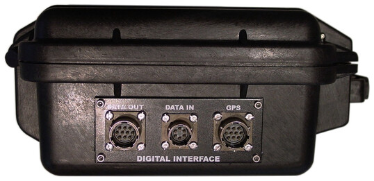
The DM24 transmits data through its DATA OUT port. This is an RS232-compatible serial link, outputting data in GCF format according to the particular configuration of the instrument. The DM24 has a default baud rate of 38,400. You can change this from the command line using the BAUD command or from Güralp Systems' control, acquisition and monitoring software package, Scream! (see Chapter 5).
A GPS connector is also provided on the front panel for attaching to a Güralp GPS receiver.
The DATA IN port can be used to access the digitiser's console over a direct serial link, or for inputting additional data streams for transmission in GCF format.
Finally, the DM24 can be supplied with an optional USB client interface for connecting to a PC. When this is present, the USB port acts as a direct replacement for the DATA OUT or console port, and appears as an additional serial port to your computer. You can configure which port is replaced from the digitiser console (see Chapter 6).
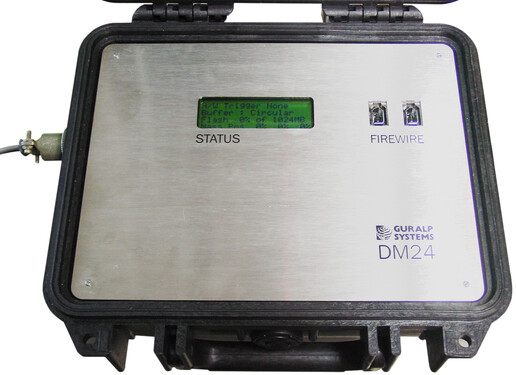
3.3.1 FireWire disks
The optional IEEE.1394 (“FireWire”) ports on the DM24 may be used to download data onto a compatible hard disk. The unit can be supplied either with standard FireWire connectors or with robust military-specification bayonet plugs (see Section 9.5 for pin-out details).
Before you can use the disk, you will need to reset it. The DM24 saves data on the hard disk in a special format, DFD, so you cannot use your PC's operating system tools to reset the disk.
You can use the DM24 itself, Scream!, or GCFXtract software to reset the disk. The very first time (for each disk), you can only use the DM24 itself. For instructions on using Scream! And GCFXtract, please see the documentation for these software packages, or their on-line help.
To reset a FireWire disk with the DM24:
Power up the DM24, and connect it to your computer's serial port.
Open its terminal console. To do this using Güralp Systems' Scream! software, right-click on the digitiser's icon (

data-terminal
and select the relevant data source from the menu.
Issue the command DISKMENU. You will see the message
Plug in FireWire cable
Plug in your disk. The DM24 will output (on the console) information about the disk as soon as it is detected.
Within the next 7 seconds, press any key to bring up the disk menu.
Key

When the reset is complete, remove the disk.


You will now be able to download data onto the disk when required.
3.4 The DM24BH borehole digitiser
When the DM24 is ordered in borehole form, it is supplied with a surface interface unit for installation at the top of the borehole. This unit takes the single data cable from the down-hole digitiser and provides standard connections for other equipment.
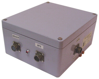
The connectors provided are:
a SENSOR connector - a ten-way military-specification bayonet socket carrying serial data, GPS and power to the sensor;
a GPS connector for attaching to your GPS receiver; and
a POWER / HOLELOCK connector which can either be connected to a source of 12 – 30 Volt DC power for supplying to the borehole instrumentation (including sensors), or to a Hole-lock Control Unit for driving the sensor's hole-lock motors. It is not usual to power the sensor and hole-lock simultaneously; once the hole-lock is engaged, you should remove the Hole-lock Control Unit and cabling so that the sensor cannot be removed.
On the reverse side, a standard nine-pin D-subminiature serial connector is provided for connecting to a PC running Scream! using a straight-through serial cable.
There is also a three-pin mains/line plug, which can power the down-hole instrumentation from a 110 – 250 Volt AC supply if required.