Chapter 4. Using the DM24
Once the DM24 is connected to your equipment, it will start producing data immediately. You can now start configuring it for your own needs. There are two ways you can do this:
using the graphical interface provided by Scream!, or
over a terminal connection (see Chapter 6).
Both methods provide full access to the major configuration options of the digitiser.
In most circumstances, you will use Scream! to operate the system. For complete information on how to use Scream! to configure and control your instrument, please refer to the Scream! user guide.
4.1 Taps
The DM24 converts analogue signals to digital data at a high sample rate, which is then reduced in steps. This process is known as decimation, and each output stage is called a tap. Taps are numbered from zero – the highest sample rate – upwards.
The highest data rate you can choose is 1000 samples/s. This rate can only be produced by Tap 0, the first tap. Tap 0 can alternatively produce data at 500, 400, 200 or 100 samples/s.
After Tap 0 there are three more taps. Each tap produces data at an integer sample rate, which must be 2, 4, 5, 8 or 10 times lower than the previous tap.
For example, the following is a possible sequence:
Tap 0 : 500 samples/s
Tap 1 : 50 samples/s (divide by 10)
Tap 2 : 10 samples/s (divide by 5)
Tap 3 : 5 samples/s (divide by 2)
The digitiser always generates all four sample rates, but it does not have to output them. You can configure any set of taps to output. You can also have different taps configured for different sensor components.
All of these configuration options are easily changed via Scream!, or you can use the terminal commands SET-TAPS and CONTINUOUS.
4.1.1 Triggering
The DM24 has a flexible triggering system. When the digitiser triggers, it can optionally output (or store – see DUAL mode in section 4.3 on page 22) additional data. Any combination of tap and component can be output as the result of a trigger.
In the example above, you might configure the sensor to output Tap 2 data (at 10 samples/s) continuously, but when a trigger is declared, to output Tap 0 data (at 500 samples/s) as well.
Using triggering helps you to use limited storage capacity or bandwidth more effectively.
The digitiser can look at the data from any tap to decide if a trigger has occurred, including taps which it does not output. Which tap you choose depends on the frequencies you want the trigger system to be most sensitive to.
There are four types of trigger.
A LEVEL trigger occurs when the absolute sample values exceed a configured value.
The commands GTRIGGERS, MICROG, and HIGHPASS control LEVEL triggering.
An STA/LTA trigger occurs when the ratio of a short-term average to a long-term average for recent data exceeds a configured value.
The commands TRIGGERS, TRIGGERED, STA, LTA, RATIOS, and BANDPASS control STA/LTA triggering.
A software trigger occurs when you issue the command S/WTRIGGER.
An external trigger occurs when external equipment signals electrically to the DM24. See section 5.1.6 for details.
The DM24 can output data streams for a period of time before the trigger starts, and after the trigger ends. The commands PRE-TRIG and POST-TRIG set these time periods.
Triggering options can also be configured through Scream!.
4.2 Streams
The DM24 organizes the data it produces into streams. Each stream has a 6-character identifier. The first four characters are taken from the Serial Number of the digitiser. (Although this setting is called Serial Number, you can change it to a different string if you wish, using Scream! or a terminal command.)
The next character denotes the component or output type:
Z, N, and E denote the vertical, north/south, and east/west components respectively.
X denotes the fourth full-rate data channel, which is provided for connection to your own monitoring equipment via the AUXILIARY connector (if present).
C denotes the calibration input channel, which replaces the X stream whilst calibration is in progress.
M denotes one of the eight slow-rate Mux (multiplex) channels. Three of these (M8, M9 and MA) are used to report the sensor mass positions. Channels MC and MD are connected to the X and Y axes of the downhole inclinometer, where fitted.
For Z, N, E, X, and C streams, the last character represents the output tap. Taps correspond to stages in the decimation process within the digitiser, allowing the DM24 to output several different data rates simultaneously. There are four taps, numbered 0 to 3; 0 has the highest data rate and 3 the lowest. Data streams end in 0, 2, 4 and 6 for taps 0, 1, 2 and 3 respectively.
If you configure the DM24 to output triggered data, these will appear in separate streams ending with the letters G, I, K or M for taps 0, 1, 2 and 3 respectively.
The DM24 also generates a stream ending 00. This is a status stream containing useful diagnostic information in plain text form (see Section 7.1).
4.2.1 Digitisers for multiple instruments
The standard DM24 has 4 full-rate channels: one per component of a triaxial instrument, plus the auxiliary and calibration channel.
Some DM24 modules, known as “6-channel digitisers”, are designed for use with two instruments simultaneously, connected to the ports SENSOR A and SENSOR B. These digitisers actually have 7 full rate data channels, including the auxiliary/calibration channel. When you enable calibration on these digitisers, the signal is passed to both instruments. All 7 channels share the same settings for the four output taps.
A 6-channel digitiser will output full-rate streams with the following final characters:
Z/N/E0 | SENSOR A at tap 0 | Z/N/E1 | SENSOR B at tap 0 | |
Z/N/E2 | SENSOR A at tap 1 | Z/N/E3 | SENSOR B at tap 1 | |
Z/N/E4 | SENSOR A at tap 2 | Z/N/E5 | SENSOR B at tap 2 | |
Z/N/E6 | SENSOR A at tap 3 | Z/N/E7 | SENSOR B at tap 3 | |
Z/N/EG | SENSOR A at tap 0, triggered | Z/N/EH | SENSOR B at tap 0, triggered | |
Z/N/EI | SENSOR A at tap 1, triggered | Z/N/EJ | SENSOR B at tap 1, triggered | |
Z/N/EK | SENSOR A at tap 2, triggered | Z/N/EL | SENSOR B at tap 2, triggered | |
Z/N/EM | SENSOR A at tap 3, triggered | Z/N/EN | SENSOR B at tap 3, triggered | |
X/C0 | Auxiliary at tap 0 | |||
X/C2 | Auxiliary at tap 1 | |||
X/C4 | Auxiliary at tap 2 | |||
X/C6 | Auxiliary at tap 3 |
Standard 6-channel digitisers have the same eight Mux channels as their 3-channel counterparts: M8, M9 and MA for the mass positions of SENSOR A, and MB to MF for your own equipment. These digitisers are designed for use with a strong-motion instrument or geophone attached to SENSOR B, and so do not expose the mass positions for this sensor. There is no calibration facility or equivalent to the X channel for SENSOR B. In addition, SENSOR B cannot be locked, unlocked, or centred.
4.3 Transmission modes
Transmission modes are an important concept on the DM24. The current transmission mode determines whether the unit stores data in its on-board Flash memory, sends them over the serial link in GCF format or does some combination of these.
You can switch between transmission modes with a console command (see chapter 6) or by using the Scream! configuration interface.
4.3.1 DIRECT
Command: DIRECT

Instructs the DM24 not to use Flash memory for storage. Instead, all data are transmitted directly to clients. An instrument in DIRECT mode still honours the GCF Block Recovery Protocol: a temporary RAM buffer always holds the last 256 blocks generated and, if a client fails to receive a block, it can request its retransmission.
If you expect breaks in communication between the instrument and its client to last more than 256 blocks, or if you want the instrument to handle breaks in transmission (rather than relying on the client to request missed blocks), you should use
ADAPTIVE mode, if you want data to stay as near to real time as possible (but do not mind if blocks are received out of order) or
FIFO mode, if you need blocks to be received in strict order (but do not mind if the instrument takes a while to catch up to real time).
4.3.2 FILING
Command: FILING

Instructs the DM24 not to transmit blocks to clients automatically, but to store all digitized data in the Flash memory. If you have chosen the RECYCLE buffering mode (see below), the memory is used in circular fashion, i.e. if it becomes full, incoming blocks begin overwriting the oldest in memory. If, instead, the WRITE-ONCE buffering mode is active, the instrument will switch to DIRECT mode (see above) when the memory becomes full.
You can retrieve blocks from an instrument in FILING mode by connecting to its terminal interface and issuing commands such as FLUSH, or through Scream! (see below).
4.3.2.1 Heartbeat messages

You can change the frequency of heartbeat messages from Scream!'s Control window, or with the command HEARTBEAT.
4.3.3 DUPLICATE
Command: DUPLICATE

Instructs the DM24 to transmit streams directly to clients as for DIRECT mode, but also to store all data into Flash storage as for FILING mode.
If a client fails to acknowledge a block, the digitiser does not attempt to retransmit it.
4.3.4 DUAL
Command: DUAL

Instructs the DM24 to transmit any continuous streams directly to clients as for DIRECT mode, but to store triggered data into Flash storage as in FILING mode.
If you choose DUAL mode but do not select any continuous streams for output, the instrument will send heartbeat messages as in FILING mode. Scream! can pick these up and download new data as necessary.
4.3.5 FIFO (First In First Out)
Command: FIFO

Instructs the DM24 to begin writing blocks to Flash memory as for FILING mode, but also to transmit data to clients. Data are transmitted in strict order, oldest first; the DM24 will only transmit the next block when it receives an explicit acknowledgement of the previous block.
If the communications link is only marginally faster than the data rate, it will take some time to catch up with the real-time data after an outage. If you want data to be transmitted in real-time where possible, but are worried about possible breaks in communication, you should use ADAPTIVE mode instead.
FIFO mode will consider a data block successfully transmitted once it has received an acknowledgement from the next device in the chain. If there are several devices between you and the instrument, you will need to set up the mode for each device (if applicable) to ensure that data flow works the way you expect.
Like all the transmission modes, FIFO mode does not delete data once they have been transmitted. You can still request anything in the Flash memory using Scream! or over the command line. The only way data can be deleted is if they are overwritten (in the RECYCLE buffering mode, see below) or if you delete them manually.
4.3.5.1 ADAPTIVE
Command: ADAPTIVE

Instructs the DM24 to transmit current blocks to clients if possible, but to store all unacknowledged blocks in the Flash memory and re-send them, oldest first, when time allows. ADAPTIVE mode is best suited for “real-time” installations where the link between digitiser and client is intermittent or difficult of access.
If the communications link is only marginally faster than the data rate, it will usually be busy transmitting real-time data. Thus, it may take a while for the instrument to work through the missed blocks. In this case, and if your client supports it, you may prefer to use the Block Recovery Protocol to request missed blocks where possible (see section 8.3).
Some software packages (most commonly Earthworm) cannot handle blocks being received out of time order. If you are using such a package, ADAPTIVE mode will not work and may crash the software.
4.3.6 Transmission mode summary
Transmission Mode: | DIRECT | FILING | DUPLICATE | DUAL | FIFO | ADAPTIVE |
Transmit continuous data: | ✔ | ✘ | ✔ | ✔ | ✔ | ✔ |
Store continuous data: | ✘ | ✔ | ✔ | ✘ | ✔ | ?1 |
Transmit trigger data: | ✔ | ✘ | ✔ | ✘ | ✔ | ✔ |
Store trigger data: | ✘ | ✔ | ✔ | ✔ | ✔ | ?1 |
Heartbeat messages: | ✘ | ✔ | ✘ | ?2 | ✘ | ✘ |
Strict time order: | ✔3 | n/a | ✔3 | ✔3 | ✔ | ✘4 |
Retransmit unacknowledged blocks: | ✔5 | n/a | ✘ | ✘ | ✔6 | ✔6 |
Notes:
Acknowledged data are not stored. Unacknowledged data are stored until they are acknowledged.
Heartbeat messages will only be sent if no continuous streams are enabled
The receiver can request a “rewind” if blocks are not received correctly but retransmission resumes in strict time order
Real-time data are prioritised over missed blocks
Up to 256 blocks can be buffered to satisfy rewind requests
The whole of flash memory is used as a retransmission buffer
4.4 Buffering modes
There are two different buffering modes which affect how the internal flash memory is utilized. Either may be used with any of the available transmission modes.
4.4.1 RE-USE / RECYCLE
Command: RE-USE
Instructs the DM24 to carry on using the current transmission mode when the Flash memory becomes full, overwriting the oldest data held. This buffering mode is called RECYCLE in Scream! and on the EAM.
For example, in DUAL mode with RECYCLE buffering, the latest continuous data will be transmitted to you as normal, and the latest triggered data may be retrieved from the Flash memory using Scream! or the command line. However, if you do not download data regularly from the Flash memory, you may lose older blocks. This mode thus lets you define the end point of the data held by the instrument.
4.4.2 WRITE-ONCE
Command: WRITE-ONCE
Instructs the DM24 to stop writing data to the Flash memory when it is full, and to switch to DIRECT mode automatically.
For example, in FIFO mode with WRITE-ONCE buffering, the station will transmit data to you continuously, but also save them into the Flash memory until it is full. Once full, the instrument will switch to DIRECT mode and continue transmitting, though no further data will be saved. This mode thus lets you define the start point of the data held by the instrument.
4.5 Downloading stored data
If you choose a transmission mode where data are stored in Flash memory, you can recover these data at a later date, using either the DM24's FireWire interface or a serial link.
Note: The FireWire interface is very much faster than the serial link: the serial link is only really useful for small, ad-hoc transfers.
The Flash memory is used as a ring buffer. Two pointers into the memory keep track of where data were last read (the “Read Pointer”) and last written (the “Write pointer”). When either pointer reaches the end of physical memory, it wraps round back to the beginning. The behaviour when the write pointer reaches the read pointer (i.e. when the memory becomes full of data, none of which have been downloaded) is governed by the commands RE-USE/RECYCLE and WRITE-ONCE, described in section 4.4.

4.5.1 Downloading over FireWire
To download data over FireWire, plug the disk in and issue the command DISKMENU from the digitiser's console. The digitiser will reply with a list of download options.
If you have not used the disk before, you will need to reset it. Resetting the disk prepares it for the DM24 to use and sets up the DFD filing system (see below). Press 
You can also use GCFXtract or Scream! to prepare a FireWire disk.
To download all the new data held by the DM24, press 
You can also download selections of data (including the entire contents of the data store, if desired) with the DISKMENU command. See Section 6.11 for more information.
The DM24 checks for a FireWire disk when it boots up. If there are enough new data waiting to be transferred (by default 128 Mb), the DM24 will automatically transfer them onto the disk. The digitiser then updates its internal pointers to mark these data as already downloaded.
This feature is particularly useful for autonomous installations: after the digitiser has been retrieved from a field experiment, simply powering it up with a prepared disk attached will make it transfer all the data it has recorded during the experiment.
While the FireWire interface is active, it will consume about 200 mA of current (from a 12 Volt supply). If you interrupt a transfer whilst it is in progress, the digitiser will re-boot and will not mark data as downloaded. Because of this, the next time you transfer data, some will be duplicated. You will not, however, lose any data.
4.5.2 Reading DM24 disks
When the DM24 saves data onto a FireWire disk, it uses a special format called DFD.
You can read these data into a PC using Scream! or the GCFXtract utility, which is freely available from the Güralp Systems Web site. Linux and Solaris command line utilities are also available for reading data from a DFD disk.
The DFD format is not the same as that used by the Güralp Systems EAM data acquisition module, which uses a FAT32-compatible journaling file system.
Güralp Systems can provide fully-tested, formatted disks with FireWire and USB connectors. Alternatively, a third-party FireWire disk may be used (although compatibility is not guaranteed).
To read a disk using GCFXtract:
Attach the disk to your computer. You can use FireWire, USB, or any other interface supported by your computer and the disk.
Run GCFXtract and select the required disk from the drop-down list, then click

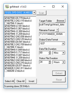
GCFXtract will scan the disk and display all the streams it finds in the selection area below. For each stream, the Stream ID and the number of blocks found are shown.
This operation requires roughly 12 Mb of available memory for every Gb of space on the disk. If you have a very large disk, your computer may have to use its hard disk to make enough space. This will slow down scanning considerably.
By default, all streams containing more than 100 blocks are selected for extraction. You can change which streams to extract by ticking or clearing the check-box beside each stream.
You can tick or clear all of the check-boxes using the


Enter a path name into the Target Directory field, or use the

Enter a format string into the Filename Format field. The syntax is the same as the format string in Scream! and full documentation is available by pressing the

Normally, GCFXtract outputs GCF files, to ensure all the information in the original data is retained. If you want to convert to a different format, select it from the Output Data Format drop-down box. GCFXtract can output in most of the formats supported by Scream!.
Data are automatically placed in time order and saved in multiple files, each file containing a contiguous segment of data. By default, data streams are recorded in files 60 minutes long. To change this to some other number of minutes, alter the value in the Data File Duration (mins) box.
If there is a gap in a data stream, GCFXtract will start a new file anyway.
Status streams are also saved in in multiple files, but have a default length of 24 hours. To change this, alter the value under Status File Duration (hours).
When you are happy with the settings, click

Clicking

When you are finished, you should exit GCFXtract and then use your operating system's standard facility for un-mounting hardware (e.g. “Safely Remove Hardware” under Windows) before disconnecting the drive.


You can also read disks with Scream!. This allows you to view data in the process of being transferred, but is slightly slower, because Scream! does not read data in strict order. To read a disk with Scream!:
Attach the disk to your computer. You can use FireWire, USB, or any other interface supported by both your PC and the disk.
Run Scream!, and select File → Setup… from the main menu. Select the Files tab.
Set the Base Directory, Filename Format and Data Format as described above. Also, if required, set the Post-processor and Granularity options to suit your requirements. Consult the Scream! documentation for details.
Select the Recording tab, and check Auto Record—Enable for Data Streams and Auto Record—Enable for Status Streams. Click OK. Scream! will remember the recording options you set in steps 3 and 4 for later occasions.
Select File → Read SCSI disk… from the main menu. Scream! will search for attached disks, and open a window with a list of all the streams it has found.
Select the streams you want to replay, and click Open. The disk will appear in the left-hand pane of Scream!'s main window, and the streams you have selected will start playing into the stream buffer, as well as being recorded.
When you have finished transferring the data, if you want to reset the disk, select File → Reset SCSI disk… from Scream!'s main menu. Select the disk you want to reset, and click OK.
4.5.3 Downloading over the serial link
Start by configuring Scream to record all incoming data by visiting the “Recording” tab of the File→Setup dialogue:

Ensure that the first four check-boxes are ticked. Next, switch to the “Files” tab and choose an appropriate base directory, file format and filename format.
Click 
Next, open a connection to the digitiser's console. To do this using Güralp Systems' Scream! software, right-click on the digitiser's icon (
data-terminal
and select the appropriate data source from the menu.
To simply download all data held in the Flash memory, issue the command
ALL-FLASH ALL-DATA DOWNLOAD
followed by
GO
This will initiate a complete download. The ALL-FLASH and ALL-DATA commands act as modifiers to tell the system what to download.
If you wish to download only a subset of data, you can replace the ALL-FLASH and ALL-DATA modifiers with other modifiers to select different streams and/or time periods:
The streams to be downloaded are specified with ALL-DATA, S/S, or STATUS-ONLY.
Any desired time period can be specified with ALL-FLASH, ALL-TIMES, or FROM-TIME and/or TO-TIME.
The parameters are illustrated in the diagram below. If you miss out a parameter, DOWNLOAD will re-use the value you last specified.

The DOWNLOAD command returns immediately, so that you can issue more commands if required. To close the connection and begin downloading with the specified selectors, issue the GO command.
Note: You can pause a download by entering terminal mode, and either restart with another GO or abort with END-DOWNLOAD.
When you complete a DOWNLOAD without specifying a time period, the DM24 adjusts the internal read pointer to mark the latest position. This is then used as the start point for the next DOWNLOAD with the command ALL-TIMES.
The various modifiers are described in detail in section 6.12.
Once the GO command has been issued, the window may close, depending on which emulator you are using. On an EAM, the data-terminal (minicom) session is closed by keying 


4.6 DM24 USB Host Operations
DM24s can be supplied with an optional USB interface. This section describes the use of this interface.
4.6.1 DM24 Mk3 USB host option

This interface enables the DM24 to record GCF data to a standard USB disk drive or Flash memory stick using the ISO 9293 FAT filing format – readable by Linux, DOS, Windows and Mac OS.
Equipment fitted with the USB Host Port connector (labelled USB BOMS – Bulk Only Mass Storage) will automatically record the current real time data to the USB device when it is plugged in.
To do this, the DM24 should be in DIRECT or DUPLICATE transmission mode so that real time data are being fed to the standard transmit buffer used for normal serial data transmission. The USB process runs in parallel with the serial transmit thread using the data in the transmit buffer. It does not matter whether the serial port is connected or not.
Other transmission modes do not pass useful data via the serial port and so cannot be used with USB devices. In particular FILING mode saves all data to the internal flash memory (for later download via the serial port or FireWire interface) and only outputs “heartbeat” status to the serial port to inform systems monitoring the port that the unit is present and operating. FIFO and ADAPTIVE modes use the internal flash as an extension to the serial transmit buffer as explained in section 4.3. As no contiguous streams are sent via the serial port in these modes, nothing will be written to the USB device.
To record data to a USB device, the system should be configured in DIRECT or DUPLICATE mode – in DUPLICATE+REUSE mode the DM24 will always have the last 64Mb or more of data in its internal flash – the firmware does not currently support transferring data from the DM24 internal flash to a USB device.
4.6.2 Formatting a USB device
If you wish to use a USB device it must be formatted with 16 Kilobyte clusters. In Windows 2000, XP and Vista open a command prompt and type:
format e: /fs:fat32 /a:16k
replacing e with the letter of the drive which you wish to format.
4.6.3 Directory structure
The system creates the following directory (folder) structure:
The main directory is \GURALP
Beneath this is a sub-directory named after the DM24's system ID (e.g. GSLA) within which will be a further sub-directory for each stream the system is configured to produce. For example:
C838Z2 tap2, vertical component at selected sample rate
C838M8 vertical component mass position
C83800 the digitiser's status stream
Data for each stream are recorded as files within the corresponding sub-directory. The file name is simply the date and time of the first sample in the file, given in the format YYMMDDHH.xxxx
For example:
08102314.gcf 2008 Oct 23 14:00 – data file
08102312.txt 2008 Oct 23 12:00 – status/text file
The amount of data in each file (granularity) depends on both the stream sample-rate and type. It can be configured using the HOURFILES command, which takes four parameters (which precede the command – see chapter 6 for details of the DM24's internal FORTH interpreter):
FAST SPS SLOW STATUS HOURFILES
FAST specifies the file size, in hours, for sample rates ≥ SPS
SLOW is the size, in hours, for lower sample rates < SPS
STATUS is the size, in hours, for status stream files.
The default settings are:
1 40 4 12 HOURFILES
With these settings, the system will start a new file every hour for streams with a sample rate ≥ 40 samples per second.
Lower sample rate streams will have files which last 4 hours – so the file names will have the sequence “YYMMDD00, YYMMDD04, YYMMDD08” etc.
Status files will have 12 hour granularity i.e. “YYMMDD00 and YYMMDD12”.
Note that status streams are recorded as plain text files with the extension '.txt'.
All other streams are recorded with the extension '.gcf' which is the same format used by 'Scream!' (i.e. a series of 1-kilobyte GCF data blocks), consequently the files can be viewed and processed by Scream!, simply by “drag and dropping” or right-clicking to select the option.
Due to bandwidth and processing limitations, it may not always be possible to record continuous streams with particularly high sample rates. Note that when triggers are in use, the sample rates of streams transmitted over the serial port will typically increase considerably. If your application involves sample rates higher than 250 samples per second, you should verify to your own satisfaction correct operation (under triggered conditions, if necessary) with your own USB devices before permanent installation.
4.6.4 System operation
USB memory sticks and disk drives normally have an LED indicating activity. This will flash as each block is written, so a few flashes every 10 seconds would be expected from a DM24 producing 100 sample-per-second data.
Since data blocks are recorded to their corresponding files in real time, only the current/latest block can be lost when a USB stick is detached; all other stream files will have been closed/saved.
When a USB stick is plugged in, the system interrogates it to determine the free space. This operation can take a minute or more depending on the capacity of the USB device.
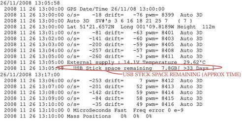
When the operation has been completed, the system reports the available space using the optional LCD and, also, in the status stream, as in the example below:
2008 10 3 13:18:49 USB Flash stick Recording started NO NAME
D:/>
USB File granularity :
For sample rates >= 40 sps : 1 hour files otherwise 4 hour files
except status ; 12 hour files
2008 10 3 13:19:52 USB Stick space remaining 3.9GB
The system will regularly (after each 5 MB of data storage – typically an hour or two of running) report the space available in GB/MB and as a predicted duration in days/hours (based on the utilization rate for the previous 5 MB).
Recording to a USB device stops automatically when there is less than 100 kB free space. To record more data, the device must be replaced with a freshly formatted one.
It is recommended that the USB device is only removed when the display shows USB free, which is followed by a bar graph indicating a 5 second countdown. The system does not automatically buffer data so, if the device is removed while the display shows USB BUSY WAIT or while it is scrolling the earlier status information, a small amount of data will be lost during the changeover. In DUPLICATE mode all data would also still be in the internal flash.
An example of a status display is shown below. This is taken from the status stream (*00) of a DM24 fitted with a USB host controller after several minutes of operation.